
8-Digit up-down counter
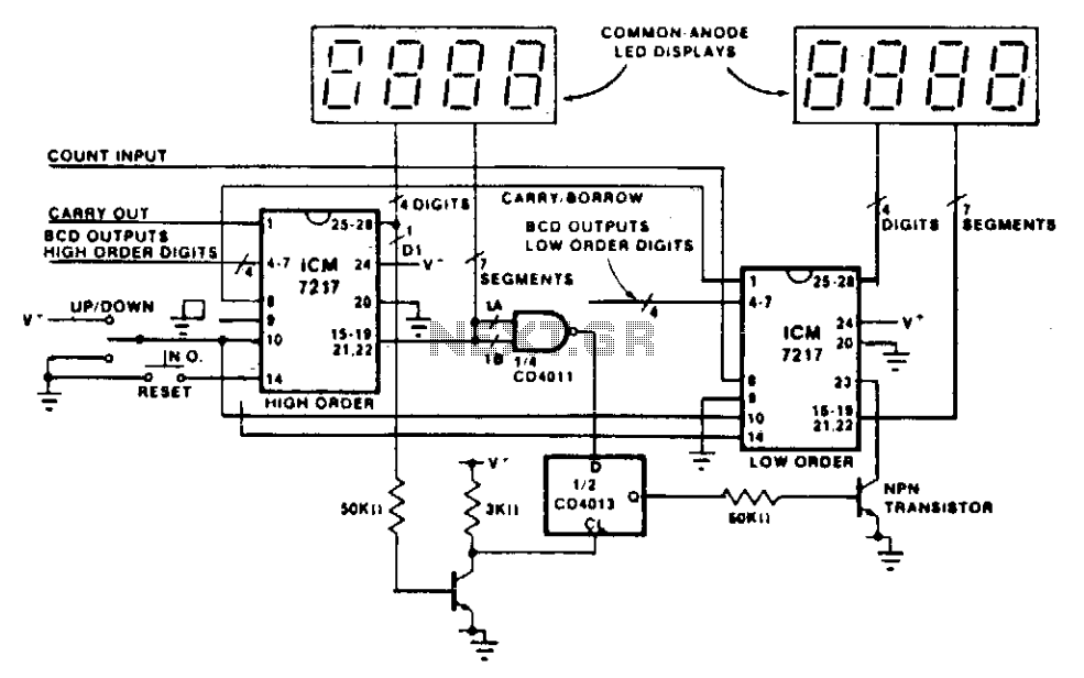
The circuit design involves a series of counters that are connected in a cascading configuration. Each counter is responsible for counting a specific range of values, and the output from one counter serves as the input to the next. This setup allows for the counting of larger numbers than a single counter could handle alone.
The key component in this design is the NAND gate, which plays a crucial role in detecting whether any of the segments (specifically segments a or b) are active. This detection is essential for maintaining the correct display of digits, particularly when leading zeros are involved. The NAND gate's output will only be low when both inputs are high, indicating that the digit is not blanked and is actively displaying a value.
The flip-flop, which is clocked by the least significant digit of the high-order counter, serves to control the leading zero blanking mechanism. When the conditions are met (i.e., the least significant digit is not blanked), the flip-flop's Q output transitions to a high state. This transition activates the NPN transistor, which is configured to inhibit the leading zero blanking on the low-order counter. As a result, the low-order counter can display its value without being suppressed by the blanking function, allowing for a more accurate representation of the overall count.
In practical applications, such a circuit is useful in digital displays where leading zeros may need to be suppressed under certain conditions. The cascading counters, along with the NAND gate and flip-flop configuration, work in harmony to ensure that the display remains clear and informative, accurately reflecting the counted value without unnecessary leading zeros.This circuit shows how to cascade counters and retain correct leading zero blanking. The NAND gate detects whether a digit is active since one of the two segments a or b is active on any unblanked number. The flip flop is clocked by the least significant digit of the high order counter, and if this digit is not blanked.
the Q output of the flip flop goes high and turns on the npn transistor, thereby inhibiting leading zero blanking on the low order counter. 🔗 External reference
Related Circuits
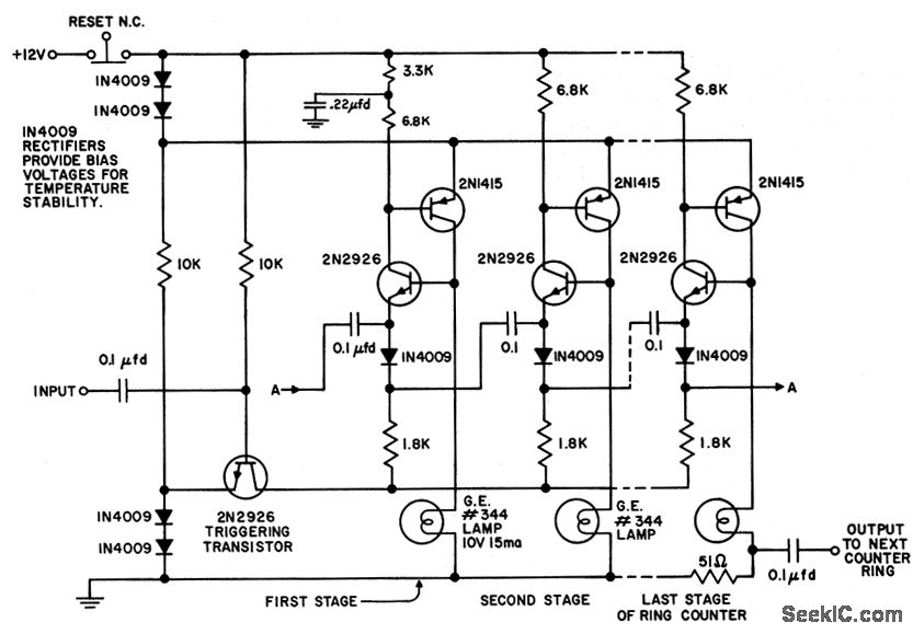
The circuit utilizes only six components per stage. By integrating counter and indicator functions, it achieves low battery consumption. Once the reset button is released, a 0.22 µF capacitor ensures that the first stage activates. Current is drawn by...
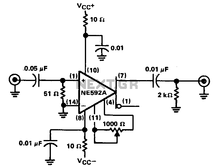
The circuit provides a voltage gain of 20 ±0.1 dB within a frequency range of 500 kHz to 50 MHz. The low-frequency response of the amplifier can be enhanced by increasing the value of the 0.05 µF capacitor connected...
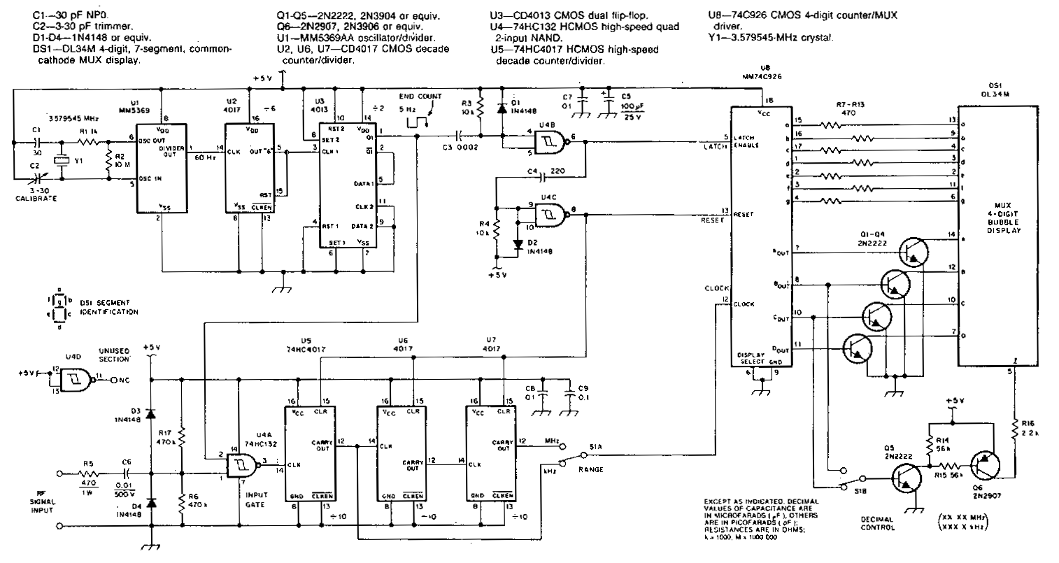
This counter features a four-digit display that can be switched to display frequencies ranging from 1 to 40 MHz, with a resolution of 100 Hz. The MM74C926 CMOS IC serves as the four-digit decimal counter, which can latch a...
This is a schematic and block diagram of a 2-MHz frequency counter. It employs an LSI counter/display driver, an LCD readout, and several logic chips for timebase and timing pulse circuitry. Transistors Q2 and Q3 form a signal input...

The Geiger tube requires a high voltage supply, which is formed by transistor Q1 and its associated components. The transformer is connected in reverse; its secondary side operates as a Hartley oscillator, with resistor RI providing base bias. Diodes...
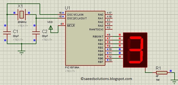
This post presents the implementation of a free-running counter using the C programming language for the PIC16F84A microcontroller. The code is structured to... The PIC16F84A microcontroller is a widely used device in various embedded applications, characterized by its 8-bit architecture...