
general purpose alarm

The alarm circuit described is a low-power, discrete design suitable for monitoring temperature variations in various environments. The use of an NTC thermistor allows for precise temperature measurements, making it ideal for applications such as frost monitoring and climate control. The circuit's architecture is built around a measuring bridge that integrates a Schmitt trigger for reliable switching under varying conditions. The clock generator plays a crucial role in periodically activating the measuring bridge, ensuring that the system remains responsive while conserving power.
The transistors used in the circuit are critical for controlling the flow of current and ensuring that the alarm is triggered only under specific conditions. The charging and discharging of capacitor C1 are vital for the circuit's operation, as they regulate the timing and enable the alarm to function correctly without unnecessary power consumption. The differential amplifier's design, enhanced by the hysteresis provided by resistors R13 and R15, ensures that the alarm system is both sensitive and stable, minimizing the risk of false alarms.
Furthermore, the choice of components, such as the epoxy resin board and low-leakage capacitor C1, reflects the design's focus on maintaining high impedance and low power consumption. The ability to adjust the response threshold with preset P1 allows for customization based on the specific application, enhancing the system's versatility. Overall, this alarm circuit represents a well-engineered solution for temperature monitoring, combining efficiency with reliability.The alarm may be used for a variety of applications, such as frost monitor, room temperature monitor, and so on. In the quiescent state, the circuit draws a current of only a few microamperes, so that, in theory at least, a 9 V dry battery (PP3, 6AM6, MN1604, 6LR61) should last for up to ten years.
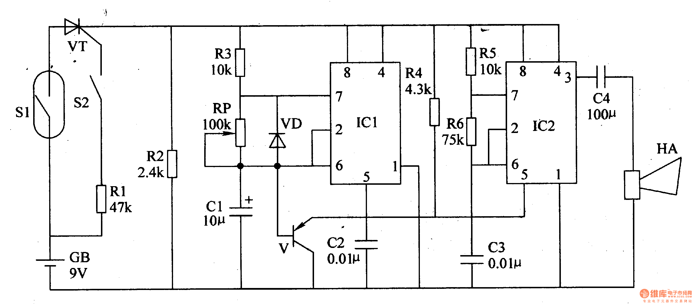
Such a tiny current is not possible when ICs are used, and the circuit is therefore a discrete design. Every four seconds a measuring bridge, which actuates a Schmitt trigger, is switched on for 150 ms by a clock generator. In that period of 150 ms, the resistance of an NTC thermistor, R11, is compared with that of a fixed resistor.
If the former is less than the latter, the alarm is set off. When the circuit is switched on, capacitor C1 is not charged and transistors T1 T3 are off. After switch-on, C1 is charged gradually via R1, R7, and R8, until the base voltage of T1 exceeds the threshold bias. Transistor T1 then comes on and causes T2 and T3 to conduct also. Thereupon, C1 is charged via current source T1-T2-D1, until the current from the source becomes smaller than that flowing through R3 and T3 (about 3 µA).
This results in T1 switching off, so that, owing to the coupling with C1, the entire circuit is disabled. Capacitor C1 is (almost) fully charged, so that the anode potential of D1 drops well below 0 V. Only when C1 is charged again can a new cycle begin. t is obvious that the larger part of the current is used for charging C1. Gate IC1a functions as impedance inverter and feedback stage, and regularly switches on measurement bridge R9 R12-C2-P1 briefly.
The bridge is terminated in a differential amplifier, which, in spite of the tiny current (and the consequent small transconductance of the transistors) provides a large amplification and, therefore, a high sensitivity. Resistors R13 and R15 provide through a kind of hysteresis a Schmitt trigger input for the differential amplifier, which results in unambiguous and fast measurement results.
Capacitor C2 compensates for the capacitive effect of long cables between sensor and circuit and so prevents false alarms. If the sensor (R11) is built in the same enclosure as the remainder of the circuit (as, for instance, in a room temperature monitor), C2 and R13 may be omitted.
In that case, C3 willabsorb any interference signals and so prevent false alarms. To prevent any residual charge in C3 causing a false alarm when the bridge is in equilibrium, the capacitor is discharged rapidly via D2 when this happens. Gates IC1c and IC1d form an oscillator to drive the buzzer (an a. c. type). Owing to the very high impedance of the clock, an epoxy resin (not pertinax) board must be used for building the alarm.
For the same reason, C1 should be a type with very low leakage current. If operation of the alarm is required when the resistance of R11 is higher than that of the fixed resistor, reverse the connections of the elements of the bridge and thus effectively the inverting and non-inverting inputs of the differential amplifier. An NTC thermistor such as R11 has a resistance at 18 °C that is about ten times as high as that at room temperature.
It is, therefore, advisable, if not a must, when precise operation is required, to consult the data sheet of the device or take a number of test readings. For the present circuit, the resistance at 18 °C must be 300 400 k. The value of R12 should be the same. Preset P1 provides fine adjustment of the response threshold. Note that although the prototype uses an NTC thermistor, a different kind of sensor may also be used, provided its electrical specification is known and suits the present circuit.
🔗 External reference
Related Circuits
This article introduces a motorcycle anti-theft alarm that utilizes the 555 timer integrated circuit. The alarm is activated when a thief attempts to move the motorcycle vertically. The circuit consists of a trigger circuit and an alarm circuit, as...

This circuit is designed to create an early warning alarm system for any form of theft that is important to the owners of a motorcycle or bicycle. This alarm system can utilize several normally open switches, such as a...
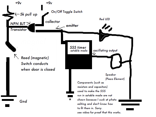
The door alarm is a compact device that activates an alarm when the door is opened. It is particularly useful for maintaining privacy, alerting individuals to the presence of others in a room while they are occupied elsewhere in...
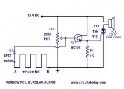
This is a simple yet effective burglar alarm circuit designed to be mounted on windows for detecting break-ins. The circuit employs a fine wire element arranged as a network within the window glass for sensing any breach. Under normal...
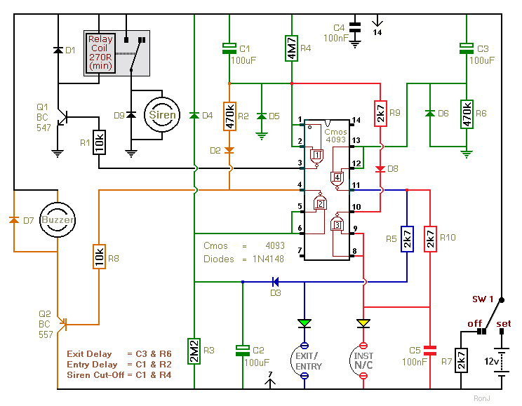
This two-zone alarm features automatic exit, entry, and siren cut-off timers. It was designed for the Beginner's Guide to CMOS Timers, providing a particularly detailed circuit description. An optional One-Time-Only module is available, which will deactivate the siren after...
A project for a morning or sunrise alarm circuit that generates a beep-beep alarm sound and flashes an LED in response to sunlight. This sunrise alarm circuit is designed to provide a gentle awakening experience by utilizing both auditory and...