
The 555 Door Alarm
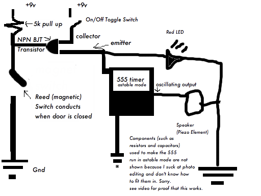
The door alarm circuit can be designed using a 555 timer IC configured in astable mode. This configuration allows the timer to produce a continuous square wave output, which can be used to drive a piezo buzzer or speaker to sound the alarm. The essential components required for this circuit include the 555 timer IC, resistors, capacitors, a power supply, and the output device (buzzer or speaker).
In the astable mode, the 555 timer oscillates between high and low states, generating a tone. The frequency of this oscillation can be adjusted by varying the resistor and capacitor values connected to the timer. For instance, two resistors (R1 and R2) and a capacitor (C1) are connected in a specific configuration to set the timing intervals. The output from the 555 timer is then connected to a transistor, which acts as a switch to control the power to the alarm device.
A magnetic door switch can be employed to detect the door's opening. This switch is typically a reed switch or a similar type that closes when the door is in the closed position and opens when the door is opened. The output from the door switch can be used to trigger the 555 timer, starting the alarm when the door is opened.
To enhance the functionality, additional features such as adjustable volume, a delay timer, or a reset button can be incorporated into the design. This allows the user to customize the alarm system according to their specific needs and preferences. Overall, the door alarm circuit is a practical solution for home security and personal privacy.My door alarm is a small device which sounds an alarm whenever the door is opened. It is ideally used when you want privacy, if you want to know if other people enter your room while you’re in another part of the house, to wake you up if someone enters your room at night, or to potentially scare away thieves who enter without permission. I don’t really know how to draw better circuits in seashore and I don’t have or know of software to make it easier for free. The components used to make the 555 timer operate in astable mode are not shown. 🔗 External reference
Related Circuits
This alarm siren circuit produces a warbling sound, suitable for use in toys or security alarms. The circuit employs two 555 IC oscillators. The first oscillator generates the audio frequency, while the second oscillator creates a modulating signal. This...
A project involving a moisture sensor alarm circuit designed to detect moisture levels in plant soil, wood, and irrigation areas. The moisture sensor alarm circuit typically consists of a moisture sensor, a microcontroller or comparator circuit, an alarm system, and...
This article describes a 2-Input alarm developed on the PIC LICK-1 Module using a Microchip PIC16F628-04. The program uses the internal 4MHz oscillator and if any other frequency is used, the timer values will need to be changed. A...

This is a door knob touch alarm designed for home security purposes. The alarm is activated when someone touches the metal door knob. However, this circuit will not function on a fully metal door. The door knob touch alarm circuit...
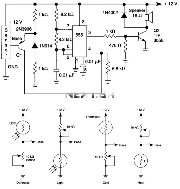
The tone generated by a 555 oscillator can be activated by heat or light, which causes Q1 to conduct transistor Q2 (TIP 3055). Q2 (TIP 3055) functions as an audio amplifier and speaker driver. The circuit utilizes a 555 timer...
This easy electronic buzzer circuit is built based on a timer that operates to generate frequency. The IC timer NE555 is used as an astable multivibrator operating at approximately 1 kHz, producing a sound when powered on. The sound...