
generating a sine wave
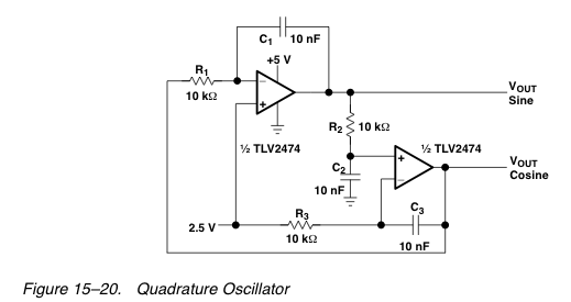
The circuit in question is designed to generate a sine wave output using operational amplifiers, specifically the TLV2472 and LM358 models. The design leverages a minimal number of components to achieve the desired frequency output. The initial configuration was set to produce a frequency of approximately 1.6 kHz, but modifications were made to lower this frequency to around 50 Hz by increasing the capacitance to 0.1 µF.
The circuit's operation relies on the feedback mechanism of the op-amps, where resistors and capacitors are configured to establish the desired oscillation characteristics. The use of 10kΩ resistors in conjunction with 100nF capacitors allows for the tuning of the frequency response. Additionally, two 330Ω resistors are employed for voltage division, ensuring that the output voltage is appropriately scaled to ±10 V.
Monitoring the output waveform with an oscilloscope reveals the performance of the circuit. Initially, the output displays a clean sine wave, indicative of effective oscillation. However, the observed clipping and overshoot suggest that the output is reaching the limits of the power supply, particularly at 5V. This phenomenon indicates that the design may require further refinement to stabilize the output and maintain a consistent amplitude over time.
The gradual fading of the signal amplitude points to potential issues within the circuit, such as component tolerances, power supply stability, or thermal effects on the op-amps. The increase in power supply voltage to 7V provided a temporary solution, yet it necessitates a more thorough investigation to identify the root cause of the signal degradation.
In summary, the circuit exemplifies a practical approach to generating a low-frequency sine wave using op-amps while highlighting the challenges associated with maintaining signal integrity and stability. Further experimentation and refinement of component values, as well as power supply considerations, will be essential for achieving reliable performance in the desired frequency range.After the recent pretty disappointing results with a transformer-based Component Tester, I`d like to try and generate a ± 10 V sine wave at approximately 50 Hz in some other way. Using as few components as possible. This is where we enter, eh, squarely into the analog electronics domain. Yes, we could generate it with an ATmega, but frankly that sounds like a bit of overkill, would require a fair amount of filtering to remove residual switching effects, and besides we`d still have to amplify it up to 10 Vpp. I`ve only just started exploring op-amps, really one superb resource on the web comes in the form of a free eBook from 2002 on the Texas Instruments site, titled Op Amps For Everyone , by Ron Mancini.
It uses very few components. This one was dimensioned for about 1. 6 KHz, so I started with capacitors ten times as large, i. e. 0. 1 µF, to lower the oscillation frequency. Here`s the result, using a TLV2472 dual op-amp: Yeah, right. Clipping like crazy, i. e. overshooting into the limiting 0V and 5V power lines. The FFT shows it`s not anywhere near a pure sine wave, even though the shape vaguely resembles one: Hmm. Looks quite good here, just tried it with an LM358. With 10k resistors, 100nF capacitors and two 330R resistors for getting V/2 I get a clean sine wave of about 170Hz.
Cosine looks also nice on my Rigol, X-Y shows a nice circle. After some minutes of measuring though, the amplitude of the signal slowly faded to zero, and now it doesn`t even start to oscillate at 5V. Raising the power suuply to 7V seems to fix that. Will have to have a look what could cause that 🔗 External reference
Related Circuits
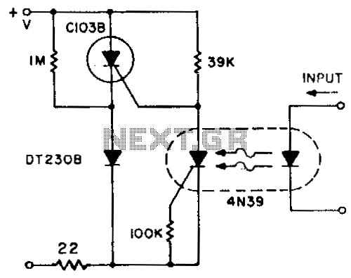
A normally closed contact circuit that provides zero-voltage switching is designed around the 4N39 SCR optocoupler. The circuit illustrates the method of modifying the normally open contact circuit by using the photo SCR to hold off the trigger SCR. The...

A single pulse signal generating circuit is depicted, which utilizes switch contacts to create a digital signal for reset or stop functions. This one-shot pulse generating circuit operates as a non-synchronous differential circuit. The single pulse signal generating circuit, commonly...
This is a wideband shortwave (SW) antenna amplifier. The frequency range spans from 1 to 30 MHz, featuring a medium gain of 15 dB. The input stage utilizes an MPF102 transistor. The wideband shortwave antenna amplifier is designed to enhance...

This design circuit functions as a sine wave oscillator, providing both sine and square wave outputs across a frequency range from below 20 Hz to above 20 KHz. The oscillation frequency can be easily adjusted by varying a single...
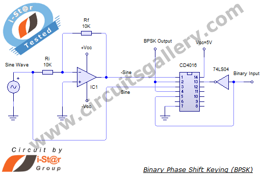
In a binary phase shift keying (BPSK) modulation scheme, the phase of a carrier signal is altered according to digital pulse signals. The BPSK modulator functions as a phase modulator, where the transmitted signal is a sinusoid with a...
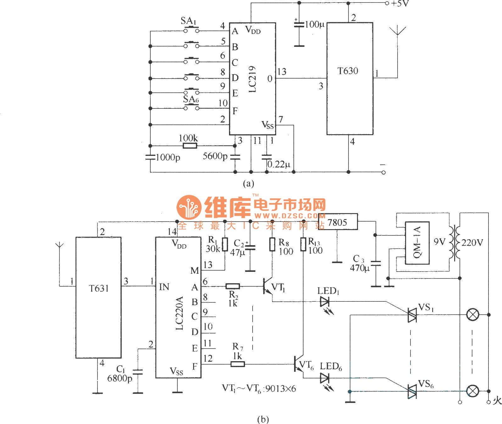
The circuit utilizes the long-wave wireless transceiver T630/T631 to manage a 6-channel load. It is characterized by low power consumption, high resistance to interference, and a simple structure. The circuit design incorporates the T630/T631 transceiver, which operates in the long-wave...