
Composed of T630/T631 long-wave wireless remote control circuit diagram

The circuit design incorporates the T630/T631 transceiver, which operates in the long-wave frequency range, facilitating reliable communication over extended distances. The transceiver is configured to control a 6-channel load, allowing for versatile applications in remote control systems, automation, and various wireless telemetry tasks.
The low-power feature of this circuit makes it suitable for battery-operated devices, extending operational life while maintaining effective performance. The high anti-interference capability ensures stable communication even in environments with significant electromagnetic noise, which is crucial for applications where reliability is paramount.
The simple structure of the circuit not only simplifies the design process but also enhances ease of maintenance and troubleshooting. The transceiver connects to a microcontroller or a similar control unit that manages the switching of the load channels based on the received signals. Each channel can be independently controlled, enabling various configurations for different applications, such as lighting control, motor activation, or sensor data collection.
Overall, this circuit presents a practical solution for implementing wireless control systems, combining efficiency with robustness in design.The circuit uses the long-wave wireless transceiver T630/T631, controlled 6-channel load. The features are low-power, high anti-interference ability and simple structure etc.. 🔗 External reference
Related Circuits
The microphone preamplifier circuit design presented in this schematic utilizes the SSM2015 produced by Precision Monolithics Inc. (PMI), which offers high amplification. The SSM2015 is a low-noise, low-distortion integrated circuit designed specifically for microphone preamplification. It features a differential input...
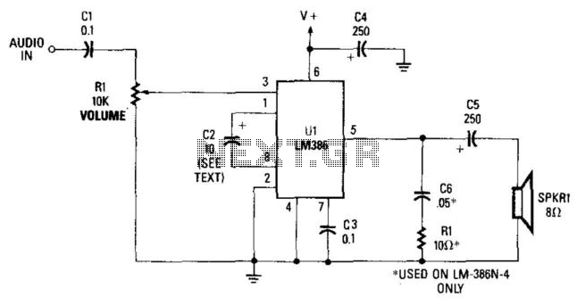
This simple receiver AF amplifier can supply several hundred milliwatts to an 8-ohm speaker. The gain is approximately 200X. If high gain is not required, C2 can be removed, resulting in a gain of 20. R1 and C6 are...
Infrared remote control operates on 115 volts AC. This circuit enables the activation of any equipment that functions on 115 volts AC. The receiver circuit is based on the Radio Shack infrared system. The infrared remote control circuit designed for...
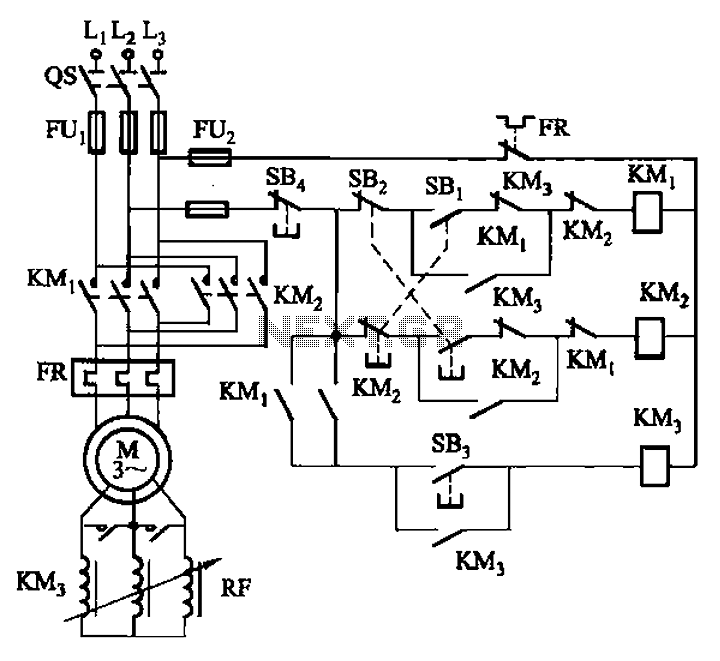
The circuit illustrated in Figure 3-166 employs a button control mechanism. To initiate forward motion, the user presses button SB1, which activates the motor rotor through a frequency-sensitive rheostat (RF). As the motor speed approaches its rated speed, a...
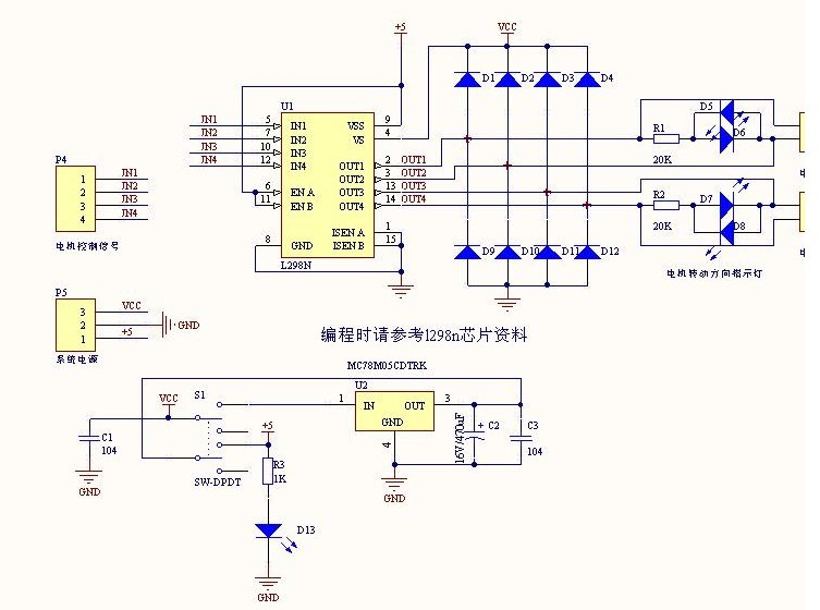
The L298N driver module incorporates the ST L298N chip, commonly utilized to drive two DC motors with voltage ratings between 3V and 30V. It features a 5V output interface that provides power for 5V single-chip circuitry and supports 3.3V...
Writing about multiple circuits in Marx, an entire new set has been discovered, referred to as "the" Marx Generator. There are diagrams available, along with a useful quote: "The main advantage of the Marx circuit configuration over a more...