
Getting more amperage from a 555 output
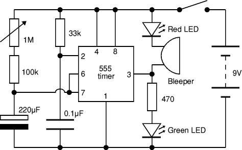
To address the issue of the pump not activating when connected to the circuit, it is crucial to understand the current requirements and the components involved. The use of a 555 timer is appropriate for timing applications; however, it does not directly supply the necessary current to drive higher-load devices like a pump. A suitable solution involves using a power MOSFET or a power NPN transistor that can handle the load current required by the pump.
The proposed circuit should include the following components: a 555 timer configured in monostable mode to generate a 4-second pulse, a power MOSFET with a sufficient current rating, and a flyback diode connected in parallel with the pump to prevent back EMF damage. The gate of the MOSFET will be driven by the output of the 555 timer, ensuring that when the timer output goes high, the MOSFET turns on, allowing current to flow through the pump.
The MOSFET's source should connect to ground, while the drain connects to the negative terminal of the pump. The positive terminal of the pump should connect to the 9V supply. Additionally, a 1MΩ resistor can be placed between the gate and source of the MOSFET to ensure it turns off completely when the 555 timer output goes low, preventing unintended operation.
It is essential to verify the current draw of the pump when connected directly to the battery to select an appropriate MOSFET. The power dissipation of the MOSFET can be calculated using the formula \( P_{D} = I_{D}^2 \times R_{DS(on)} \), where \( I_{D} \) is the current through the pump and \( R_{DS(on)} \) is the on-resistance of the MOSFET. Ensure that the selected MOSFET can handle the calculated power dissipation within its thermal limits.
In summary, the integration of a suitable MOSFET with the 555 timer circuit, along with proper current handling and protection measures, should resolve the issue of the pump not activating and provide reliable operation for the drink mixer application.A drink mixer inspired by BAR2D2, I am using a gravity fed pump that is capable of running on a 9v battery. I am using a circuit with a 555 timer to control how long the pump will run. When I hook the pump directly to the battery the pump runs perfect. When I plug it onto my circuit, I get nothing. It turns out I am not getting enough amperage to run the pump. When I put power to the circuit I want the pump to run for 4 seconds which will fill up a cup. the green LED is where I am putting the power leads that go to the pump. When I use the green LED in the circuit the circuit works perfectly. When I replace it with the pump the pump doesn`t come on. When I hook the pump to the battery the pump works. My best guess is the pump needs 2 amps to run and it is not getting that. "When I hook the pump directly to the pump the pump runs perfect" - are you sure about that Also not sure about the "pnp" tag on this question - is there a reason for that angelatlarge Apr 20 `13 at 22:57 Without a circuit diagram, any answer or comment is merely a blindfolded dart toss. So, here`s my toss: have you considered using a relay Alfred Centauri Apr 20 `13 at 23:28 @TrishaWrightBuck slow down and read what folk are saying and examine what you are telling us.
For a start read what you said: "When I hook the pump directly to the pump the pump runs perfect" - this does not make sense and, trying to fathom out what you have tried without a scheme of some sort doesn`t make much sense either. Help us help you. BTW I`m not a councillor but because I like drink I`m prepared to help! Andy aka Apr 20 `13 at 23:44 @Andyaka: The OP has been unable to have a drink, hence slowing down may be difficult.
We need to organize an emergency airlift of motorized drinks to the OP`s current location. angelatlarge Apr 21 `13 at 0:01 Did you use a power NPN transistor which can handle the collector current, with an adequate heat sink Did you give it enough base drive so that it is fully saturated Those three things will lead to a "one use only" transistor: inadequate rating; inadequate heat sinking for the device, current, and ambient temperature; inadequate turn-on, allowing a significant voltage drop across the transistor at a current that is still large. I would not use a relay here because the gravity fed pump (valve, really ) runs on a small voltage. There is no need for the isolation. Kaz Apr 21 `13 at 3:11 Ill assume is that you have an unregulated supply, and you are powering everything at 9V.
This is enough to correctly bias any N channel MOSFET. What youll do is connect the output of your 555 directly to the mosfet`s gate, the mosfet`s source to gnd, and the mosfet`s drain to the pump`s negative terminal. And you will need two extra components, first and most important a 1n4007 diode in parallel with the pump, with the cathode on the pump`s positive terminal.
And also, a 1Meg resistor between the mosfet`s gate and source. The only thing you need to make sure is that the mosfet can handle the current needed by the pump. To do that, you need to measure the pump`s current while connected to the battery directly. Now, you need a mosfet whose Rdson times that current squared (this will be the mosfet`s on state power dissipation in your circuit) is less than the maximum power that the device can dissipate. For a TO220 Mosfet, that will be in the order of 0. 5-1W depending on how hot you want it to run. EDIT: The 1M pull-down is used to ensure that the MOSFET is properly switched off, draining the charge that may remain in the gate.
Some might say that in this case it is not needed because the 555`s output is push-pull, and can properly drive the gate to gnd. But I view this as decoupling caps, you always have to use them or you`ll regret it. Besides, in this case there is a reason to use it; when power is removed, I wouldn`t trust the 555 to drive the output low, and you want that M
🔗 External reference
Related Circuits
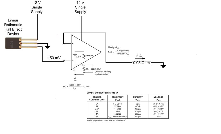
The proposed approach would dissipate (12V)(3A) = 36 watts, which results in significant heat generation in the circuit. This necessitates consideration of two alternatives: 1) Operating the op-amp at a lower supply voltage, if feasible, or 2) Utilizing a...
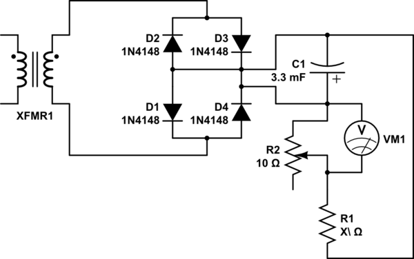
Connect the 25VAC output to a diode bridge with a capacitor (3300uF - 25V) to the positive and negative pins to eventually obtain 25VDC. The goal is to reduce the 25VDC to 17VDC. A voltage divider with a variable...
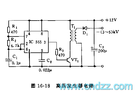
The high voltage generator depicted in figure 16-18 utilizes the 555 timer IC as its primary component. The oscillating voltage produced is enhanced through a step-up transformer. The astable multivibrator configuration comprises the 555 timer along with resistors R1...
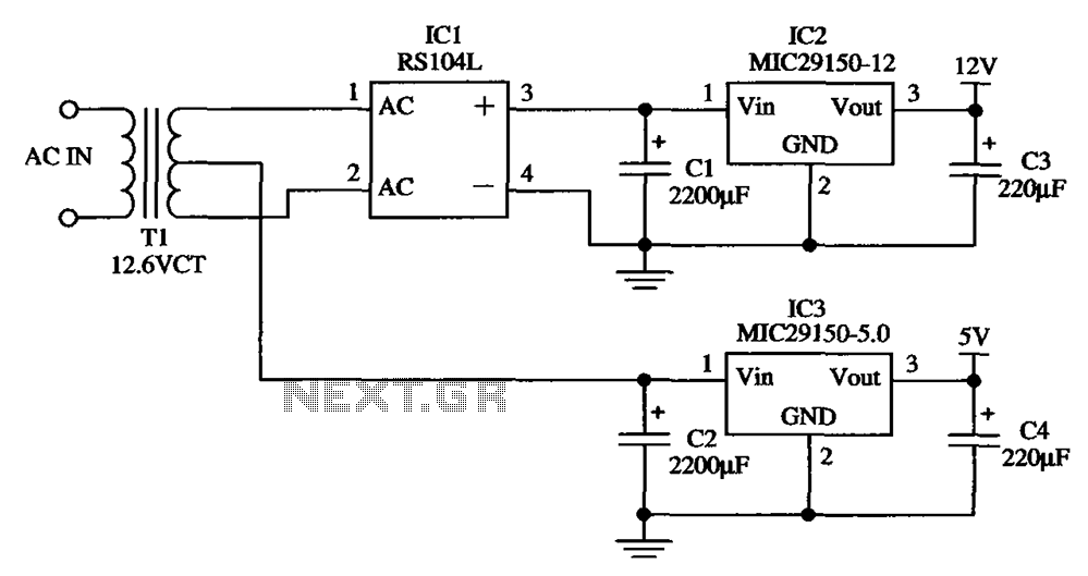
The low-cost dual output voltage regulator circuit is composed of two Micrel company regulators, the MIC29150-12 and the MIC29150-5.0. The dual output voltage regulator circuit utilizes the MIC29150 series from Micrel, which are low-dropout (LDO) voltage regulators designed for various...
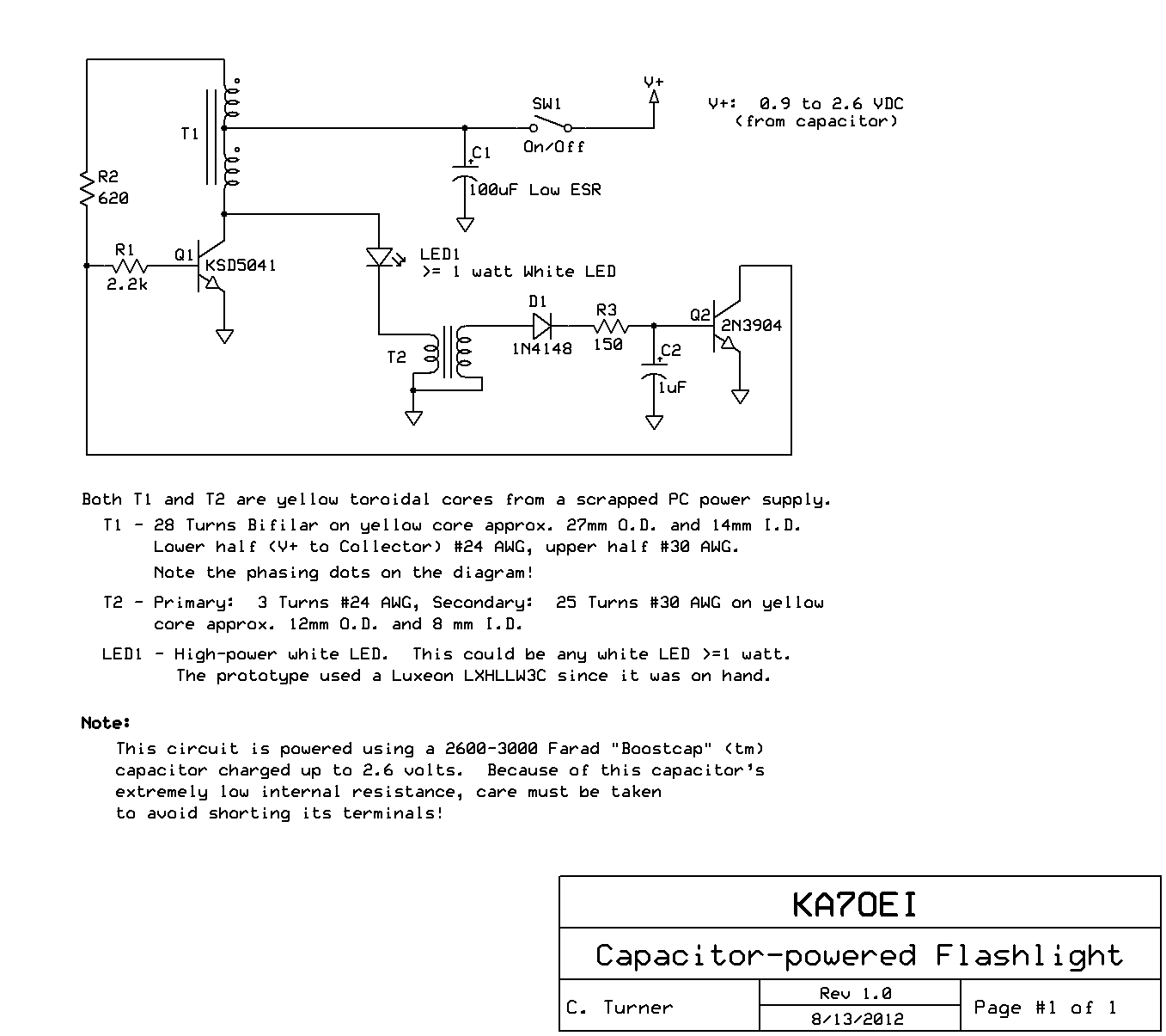
The inexpensive flashlight utilized a small (0.22 Farad) capacitor for energy storage, which provided approximately 6.6 Joules of energy, significantly less than 1/1000th of the energy contained in a single AA alkaline cell. As a standard "super capacitor," it...
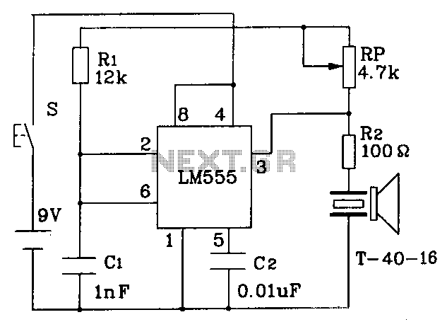
The circuit operates at a distance of 3 feet from the oscillating pulse output of a 555 timer generating a 40kHz signal, driving a T-40-16 transducer to emit ultrasonic signals at the same frequency. The circuit is powered by...