
Circuit to convert a voltage output of a Hall device to a current
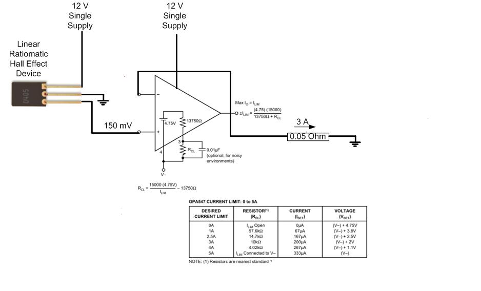
The circuit design involves a Hall effect sensor, specifically the Allegro A1321, which is utilized to measure current through a conductor. The sensor operates by generating a voltage proportional to the magnetic field produced by the current flowing through the conductor. The sensor's output is connected to the Burr-Brown OPA548 operational amplifier, which is configured to provide a gain of 40, amplifying the Hall sensor's output to a usable level. The output of the amplifier is then fed to a load resistor (R3), which is strategically selected to handle the power dissipation while providing an adequate voltage drop for the circuit's operation.
In terms of power dissipation, the design must account for the significant heat generated by the amplifier when operating at 12V and driving a 3A load. The total dissipation of 36 watts necessitates the incorporation of a large heat sink to maintain operational stability and prevent thermal shutdown. The choice of components, including the resistance values for R3, must be made with careful consideration of their thermal characteristics and the impact on measurement accuracy.
To ensure precision in current measurement, the circuit employs a Kelvin connection for the resistors, minimizing the impact of lead resistance and ensuring that the voltage drop across R3 accurately reflects the current flowing through it. The layout of the circuit should also be optimized to reduce electromagnetic interference and noise, which could affect the performance of the Hall sensor and the amplifier.
Overall, this circuit design aims to achieve a reliable and accurate current measurement system, capable of operating within specified parameters while managing heat dissipation effectively.The approach you have shown would dissipate (12V)(3A) = 36 watts. This is quite a lot of dissipation so the complete circuit will get HOT. There are two possible alternatives: 1) Run the op amp from a lower supply voltage, if available. 2) Use a class-D type amplifier. The Hall Device voltage represents a current in a separate conductor of 5 Amps. That 5 amp current produces a magnetic field in a gapped toroid core of about 30 G and the Hall device sensitivity is 5 mV/G. The requirement is to measure the current over a narrow range (4 to 6 A) very accurately (<0. 1%). The Hall device is an Allegro A1321 and the output is push-pull. I don`t know if it is possible to avoid the ground reference for the output resistor. The current measuring instrument is a Yokogawa WT 1600 power meter which has a current transformer input stage with 25 milli-Ohms of resistance.
The 50 milli-Ohm includes some added resistance to achieve the correct output current. It sounds as if the 0. 05 ohm load is a winding of a current transformer, correct It would seem that this load could then be floating and would not need to be ground referenced. This could simply the circuit used to drive the 3A current. Your power calculation is the power dissipated by the 0. 05 ohm load which is small by comparison. The power that must be dissipated by the amplifier drive circuitry is 36 watts at 12V operation. (Actually about 35. 5 watts, accounting for the power delivered to the 0. 05 ohm resistor. ) This will require a large finned heat sink. I just want you to consider whether this is practical before we design a circuit. Another comment. the spec on the Allegro Hall device shows an operating voltage of 5V with an absolute max of 8V. It should not be powered from 12V as you show it. Furthermore it is shown to be on last-time-buy status on the Allegro site. I didn`t show the voltage divider that I use to decrease Vcc for the A1321 to prevent clutter on the diagram.
I have A1324 units on order (delivery in 6 weeks) and a stock of A1321 devices on hand. The Burr-Brown OPA548 operates on any (single) voltage from +8 to +60 V and the performance is not significantly affected over the full range of the supply voltage. Power loss is not an issue. Here is a possible circuit for your consideration. I agree with your selection of the OPA548. The 150mV signal is amplified by a gain of 40 and impressed on R3, making 6V on R3. The 3A in this resistor flows through your load, RL. R3 is chosen to drop half the supply voltage on itself rather than the amplifier. This splits the 35. 5 watts of dissipation between R3 and U1. Both will still get hot. The accuracy and temperature stability of R3 will directly affect accuracy. The current flowing in R1 + R2 creates a tiny error but it`s proportional to the signal value and can be neglected.
Grounding technique will be very important due to the low value of R3. Kelvin-type connections of R2 to the high side of R3 and R1 and the input signal to the low side of R3 are critical. I would not use a fuse instead of the amplifier`s internal current-limit circuit. With semiconductors, it is always a race between the silicon and the fuse to see which one blows first.
The silicon almost always wins. All content and materials on this site are provided "as is". TI and its respective suppliers and providers of content make no representations about the suitability of these materials for any purpose and disclaim all warranties and conditions with regard to these materials, including but not limited to all implied warranties and conditions of merchantability, fitness for a particular purpose, title and non-infringement of any third party intellectual property right. TI and its respective suppliers and providers of content make no representations about the suitability of these materials for any purpose and disclaim all warranties and conditions with respect to these materials.
No license, 🔗 External reference
Related Circuits
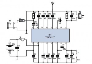
The FM Radio Receiver IC TDA 7012T is a straightforward component that offers excellent sensitivity and selectivity for FM radio reception. This single-chip FM receiver, known as IC TDA7012T, requires minimal additional components to construct an FM receiver. The...
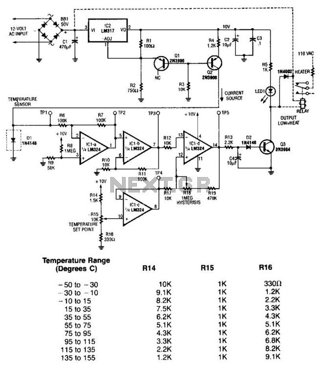
The LM35 temperature sensor outputs 10 mV/C for each degree Celsius above 0°C. At 20°C, the output voltage is calculated as 20 × 10 = 200 mV. The circuit consumes minimal power. Additionally, the load resistance should not be...
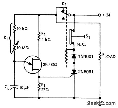
A time delay circuit utilizing a Unijunction Transistor (UJT). The maximum time delay is adjustable via a 10 MΩ potentiometer, allowing the time delay to be configured from less than one second to approximately 2.5 minutes, as referenced by...
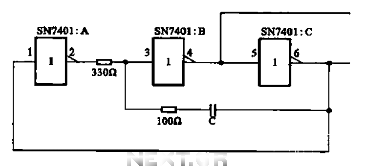
The clock signal generating circuit utilizes an RC configuration, commonly applicable in most TTL systems. This circuit requires a set of six inverters, specifically three inverters from the SN7401 series. The clock frequency is determined by the values of...
The circuit is placed parallel with the exit of power amplifier and gives the level of signal from output. Changing resistance R1 in the input circuit, we adapt the indication of power in the resistance of loudspeaker that we...
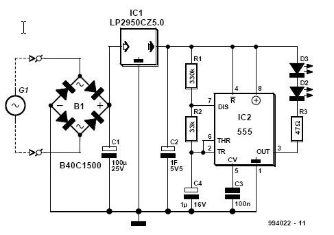
This article is relevant only to readers whose bicycle lights are powered by a dynamo. The regulations regarding bicycle lights in the United Kingdom are stricter than in many other countries, making dynamos a rarity in the UK. For...