
555 high voltage generator circuit
The high voltage generator circuit operates on the principle of pulse-width modulation (PWM) generated by the 555 timer in astable mode. In this mode, the timer continuously switches between its high and low states, creating a square wave output. The frequency of oscillation is determined by the values of resistors R1 and R2, and capacitor C1, which set the charge and discharge times of the capacitor, thereby influencing the duty cycle and frequency of the output waveform.
The output square wave from the 555 timer is fed into the base of the transistor VT1, which acts as a switch. When the 555 timer output goes high, VT1 is turned on, allowing current to flow through the primary winding of transformer T1. This action induces a magnetic field in the transformer, which, due to the principles of electromagnetic induction, generates a higher voltage in the secondary winding.
Transformer T1 is critical in stepping up the voltage to the desired high voltage level. The turns ratio of the transformer determines the increase in voltage, and careful selection of this ratio is essential to achieve the required output voltage without exceeding the ratings of the components involved.
Overall, this high voltage generator is suitable for applications where a compact and efficient voltage boosting solution is required. It is important to ensure that all components, especially the transformer and the transistor, are rated for the expected high voltage output to ensure safe and reliable operation. Proper heat dissipation measures should also be considered for the transistor to prevent thermal overload during prolonged operation.As the figure 16-18 shows, the high voltage generator uses the 555 as the core, the oscillation voltage is boosted by the step-up transformer. The astable multivibrator is composed of the 555 and R1?R2?C1, the oscillation frequency f=1.44/(R1+2R2)C1, it is about 2000Hz.
The 555 oscillation square-wave is amplified by VT1, and is boosted by transformer T1, an.. 🔗 External reference
Related Circuits
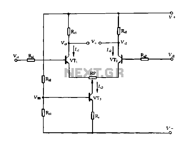
A differential amplifier with a constant current source is illustrated in Figure 1-27. As long as capacitor C3 is maintained at a constant value, capacitors C1 and C2 cannot be simultaneously increased or decreased, preventing voltage drift. The differential...
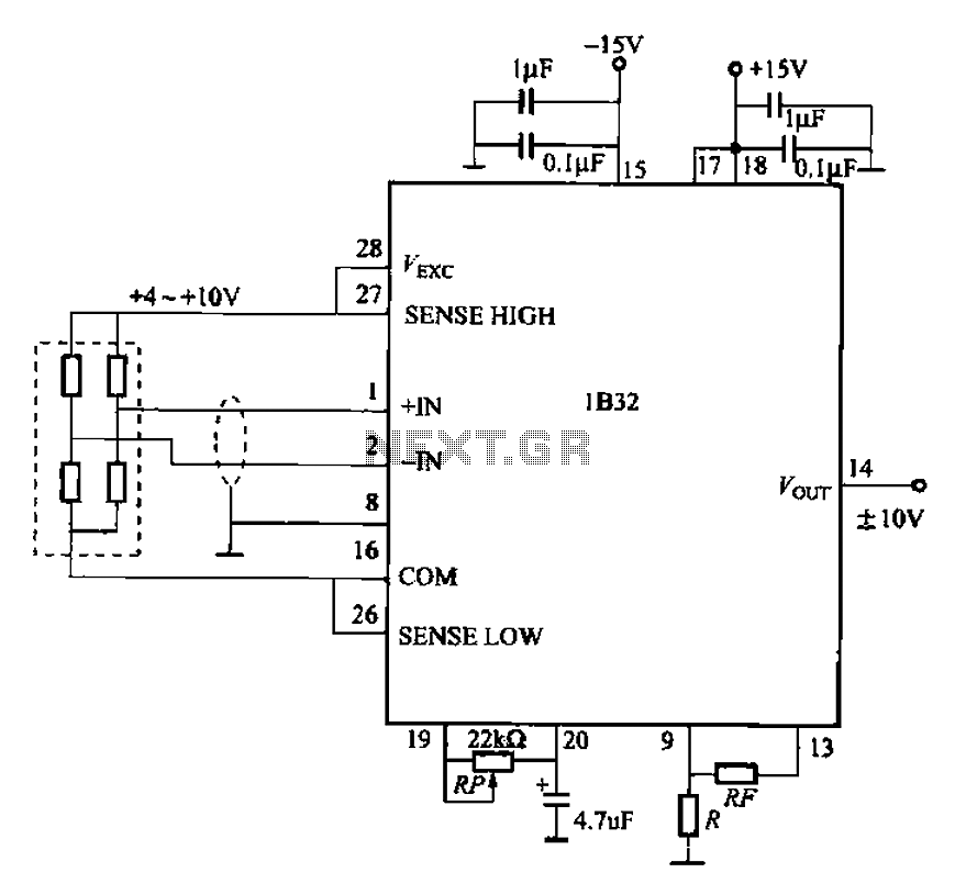
The circuit for bridge measurements is straightforward, as illustrated in the figure. The sensor bridge drive voltage can be adjusted between +4V and +10V, depending on the specific requirements of the sensor. Two fixed gain options of 333.3 and...
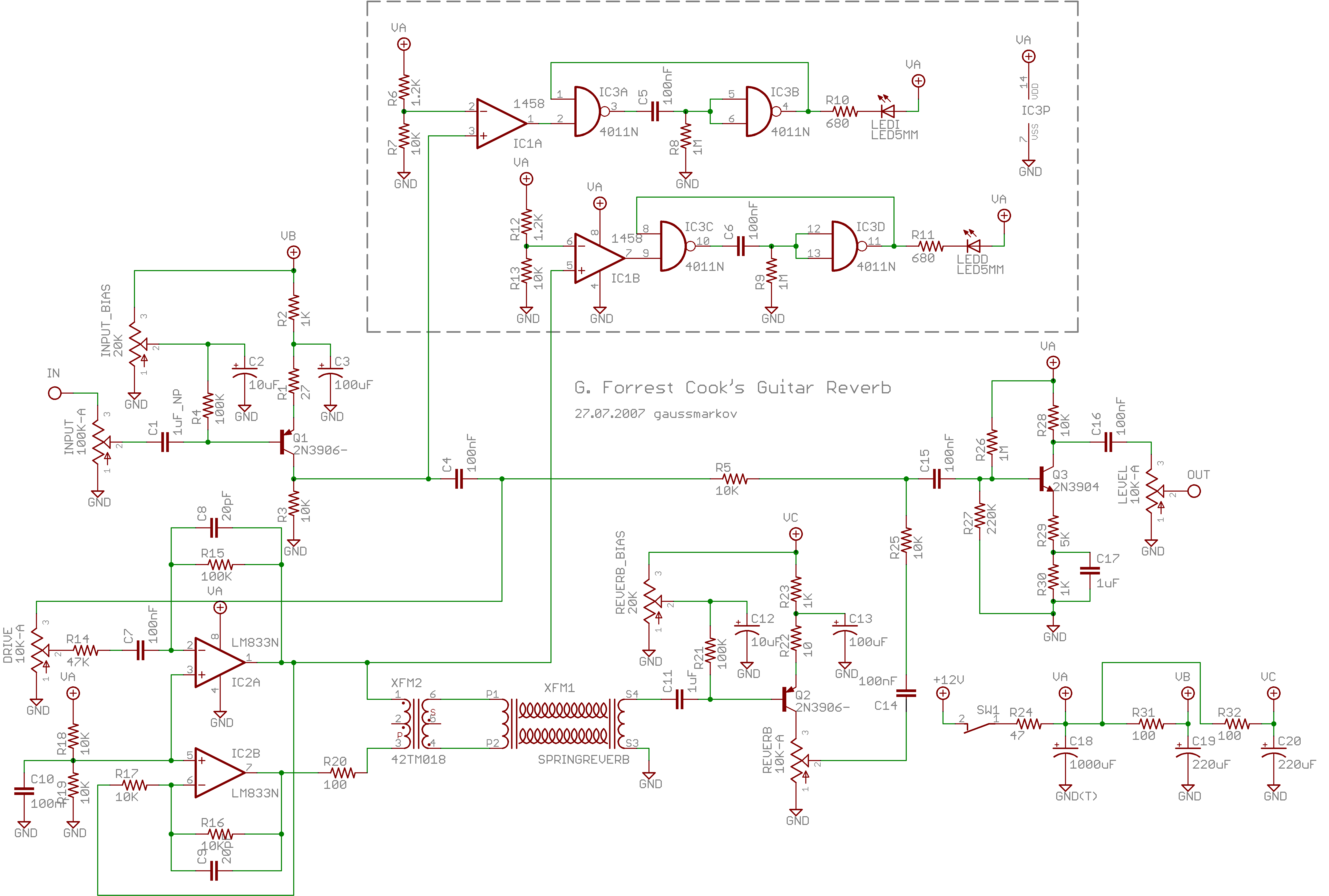
Spring reverb produces a clean and natural sound, often perceived as exceptionally good for a spring reverb. However, when the reverb springs are struck forcefully, they create explosive dub-like effects. Spring reverb is an analog sound processing technique that utilizes...
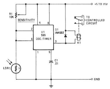
The following circuit illustrates a Photo Alarm Electronic Circuit. This circuit is based on the 555 Timer IC and incorporates features such as an LDR (light-dependent resistor). The Photo Alarm Electronic Circuit utilizes a 555 Timer IC configured in monostable...
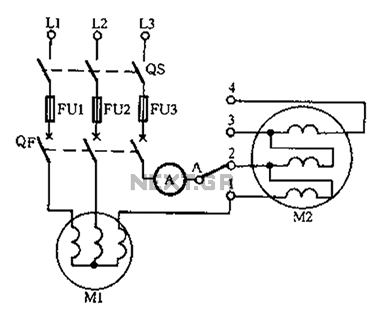
Below is a circuit diagram for detecting motor winding current imbalance during the drying process. The circuit diagram is designed to monitor the current flowing through the windings of a motor used in drying applications. This imbalance detection is crucial for...
A versatile circuit of an IF signal generator that may be of interest to radio hobbyists and professionals alike. Transistors T1 and T2 form an astable multivibrator oscillating in the audio frequency range of 1 to 2 kHz. An...
Warning: include(partials/cookie-banner.php): Failed to open stream: Permission denied in /var/www/html/nextgr/view-circuit.php on line 713
Warning: include(): Failed opening 'partials/cookie-banner.php' for inclusion (include_path='.:/usr/share/php') in /var/www/html/nextgr/view-circuit.php on line 713