This circuit is designed to detect microwave sources, such as microwave ovens, satellite communication devices, and mobile phones. It provides audio-visual indications upon detecting microwaves in the gigahertz band, which encompasses frequencies between 2 GHz and 300 GHz. Microwave ovens typically operate around 3 GHz in the UHF range, while mobile phones and satellite devices generally utilize signals between 2 and 3.5 GHz. The circuit leverages fundamental principles of electromagnetic radiation and magnetic induction. Electromagnetic radiation consists of oscillating electrical and magnetic field components that are perpendicular to each other and to the direction of energy propagation. When an inductor coil paired with a capacitor is positioned in the path of electromagnetic radiation, the capacitor stores electrical energy while the inductor stores energy in the magnetic field created by the coil windings. The magnetic field induces a current in the inductor through the skin effect, which is utilized in this circuit to detect microwave radiation. A pickup coil (L2) and a capacitor (C2) form the signal detector that resonates in response to microwave radiation, generating a small voltage (approximately 2 millivolts) across signal diodes D1 and D2. Due to the weak voltage produced by the sensor assembly, a differential amplifier (IC1) is employed to amplify the signal. The CA3130 (IC1) is configured as a differential amplifier with balanced inputs established by R1 and the sensor assembly. The pickup coil is directly connected to the inverting and non-inverting inputs of IC1, allowing a minute current in the pickup coil to create a potential difference across IC1's inputs, resulting in a high output. The CA3130 is a CMOS high-speed switching operational amplifier featuring gate-protected p-channel MOSFET transistors at the inputs, enabling it to switch the output high with a current as low as 2 pA. An adjustable resistor (VR) is included for offset adjustment and to bias the internal circuitry of IC1, ensuring that its output remains low under normal conditions. Resistor R3 provides negative feedback to the amplifier. When bursts of microwave energy strike the loop aerial (L1), the energy is transferred to the inductor coil (L2), inducing an alternating current in the inductor that flows to IC1's inputs through C1 and D1. Signal diodes D1 and D2 (BAT 43 Schottky diodes) direct the induced current into IC1's inputs, while capacitor C3 stabilizes the non-inverting input of IC1. D1 and D2 also serve the purpose of signal detection. Typically, the inputs of IC1 are biased by R1 and C2, and its output is set low by VR. When microwave radiation is detected near the sensor coil, it generates a current that disrupts the balance of IC1's inputs, causing the output to switch high and activate the switching transistor (T1). This triggers the buzzer and illuminates an LED, indicating the presence of microwaves. The sensor assembly is a critical component of the circuit and must be constructed carefully. L2 can be a miniature coil with a ferrite core, which may be salvaged from an old CFL, while L1 can be a common dipole TV antenna. Upon initially powering the circuit, VR must be adjusted to keep the buzzer and LED off. The circuit is designed to be immune to other forms of RF radiation but is capable of detecting gigahertz signals from an active mobile phone. There is significant potential for experimentation, such as testing different values for C1, C2, D1, and D2, or using various types of coils in place of L2. Additionally, incorporating a TV signal booster between the dipole and the circuit input may yield further enhancements.This circuit is useful to detect microwave (gigahertz signal) sources like microwave oven, satellite communication devices, Mobile phones etc. It gives audio visual indications when it detects the Microwaves in the Gigahertz band. Microwave is the form of EM radiation with frequencies between 2 GHz and 300 GHz. Microwave oven uses UHF around 3 GHz in the S band. Mobile phones and Satellite devices generally use 2 to 3. 5 Gigahertz signals. The circuit exploits a few simple scientific facts about EM radiations and Magnetic induction. Electromagnetic radiation has both electrical and magnetic field components which oscillate in phase perpendicular to each other to the direction of energy propagation. If an inductor coil with a parallel capacitor is placed in the path of EM radiation, the capacitor stores electrical energy and inductor stores energy in the magnetic field induced by the coil windings.
The magnetic field induces a current in the inductor through` Skin Effect`. This phenomenon is exploited in the circuit to detect the energetic microwave radiations. A pickup coil (L2) with a capacitor (C2) forms the signal detector which resonates in response to the microwave radiation and generates a minute voltage (around 2 milli volts) along the signal diodes D1 and D2. Since the voltage generated by the sensor assembly is too weak, a differential amplifier (IC1) is used to amplify the signal.
CA 3130 (IC1) is designed as a differential amplifier with balanced inputs set by R1 and the sensor assembly. The pickup coil is directly coupled to the inverting and non inverting inputs of IC1, so that a minute current in the pickup coil can generate a potential difference across the inputs of IC1 and its output switches high.
CA 3130 ( IC1) is a CMOS version high speed switching Operational amplifier with gate protected p- channel MOSFET transistors in the inputs. This makes the IC suitable to switch the output high with a current as low as 2 pA. VR is provided for the offset adjustment and bias the internal circuitry of the IC1, so that its output is ordinarily held low.
Resistor R3 gives some negative feed back to the amplifier. When the bursts of microwave impinge on the Loop aerial (L1, it pickup the energy from the radiation and transfer it to the inductor coil (L2) This creates an alternating current in the inductor which passes to the inputs of IC1 through C1 and D1. Signal diodes D1 and D2 (BAT 43 Shottky Diodes) directs the induced current into the inputs of IC1 and the capacitor C3 provides suitable stabilization of the non inverting input of IC1.
Diodes D1 and D2 also perform the function of signal detection. Normally the inputs of IC1 are biased by R1 and C2, and its output is set low by VR. When there is a microwave radiation near the sensor coil, it generates a current that upsets the balance in the inputs of IC1 and its output switches high to drive the switching transistor T1. Buzzer starts sounding and LED lights indicating the presence of Microwave. Sensor assembly is the important part of the circuit and should be prepared carefully. L2 can be a miniature coil with ferrite core. This can be procured from an old CFL. L1 is the common dipole TV antenna. When the circuit is first powered up, VR needs adjustments to keep the buzzer and LED off. The circuit is immune to other forms of RF radiations but can detect the Giga Hertz signals from an active mobile phone.
There is lot of room for experimentation. To detect different frequencies, experiment with different values of C1, C2, D1, and D2. Also try different types of coils in the place of L2. Try to use a TV signal booster between the dipole and input of circuit. 🔗 External reference
The circuit is designed to set a delay time based on the voltage Us and the resistor R. In this configuration, S1 acts as the discharge switch for capacitor C. When switch S1 is closed, the stored charge in...
Ambient light is increasingly being utilized as an energy source. To assist designers in developing such systems, this circuit effectively measures ambient light intensity across four decades of measurement. The design is cost-effective, and with the sensor housed in...
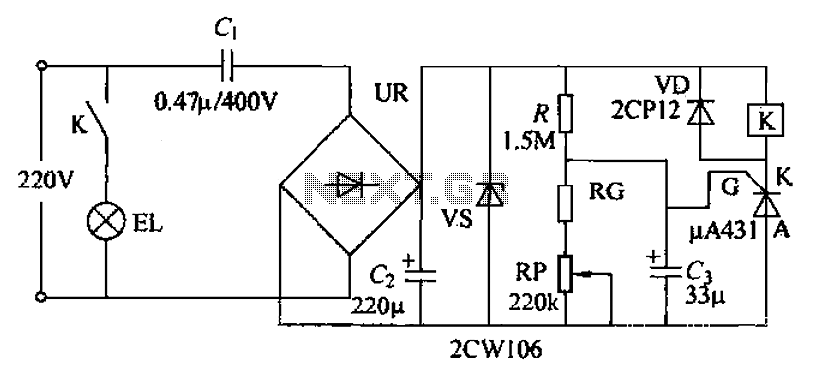
The circuit utilizes a 220V AC voltage input that is processed through a capacitor (C1) for bucking, followed by a rectifier bridge (UR) which acts as a barrier-wave rectifier. A filter capacitor (C2) is used to smooth the output...
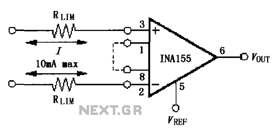
The input current protection circuit is illustrated in FIG, utilizing INA155/156. The INA155 features internal electrostatic discharge (ESD) protection diodes that become active when the input voltage exceeds the supply voltage by 500mV. In this scenario, the protection diodes...
This circuit regulates a DC power output and has a wide range of applications. It can be utilized to control the speed of a motor, a pump, a toy train, or the brightness of an LED or lamp. Essentially,...
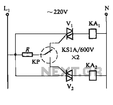
To prevent the failure of electric contact pressure thermometer contacts due to singeing, it is advisable to enhance the contacts, as illustrated in Fig. 11-60. Specifically, the output termination table for DC control utilizes two two-way thyristors or a...
We use cookies to enhance your experience, analyze traffic, and serve personalized ads.
By clicking "Accept", you agree to our use of cookies.
Learn more