Glolab 4 Bit Encoder/Decoder for Wireless and Infrared
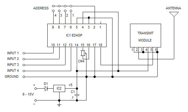
The Glolab ED4GP microprocessor-based Encoder/Decoder is designed for use with wireless modules, infrared remote controls, and other devices that operate with serial input and output data. It can function as either an encoder or a decoder by connecting pin 3 to either low (VSS) for encoding or high (VDD) for decoding. The device can encode four bits of data and four address bits, allowing for 16 addresses. When operating as an encoder, data encoding is triggered by any or all input pins going low. In decoder mode, either momentary or latched data outputs can be selected by adjusting pin 12 to either high or low. A momentary valid transmit output indicates when valid data is being received. The ED4GP remains in a low power mode, drawing only 1 microampere when not actively encoding or decoding, making it suitable for battery-powered applications. It operates at 5 volts and consumes approximately 3.5 milliamperes (excluding loads) when active. As an encoder, it activates when an input pin is pulled low, while as a decoder, it activates upon receiving serial data. An internal clock is generated by a 4 MHz ceramic resonator connected to pins 15 and 16, providing accurate frequency control and improved serial data synchronization compared to resistor-controlled oscillators used in some encoders and decoders. This design facilitates higher speed data transfer without the risk of lost data. A recommended resonator type, which has three pins and includes internal capacitors to minimize external components, is available from suppliers such as Digi-Key, ECS (part number X902), Panasonic (part number PX400), and Mouser (ECS part number 520-ZTT400MG), as well as Glolab (part number CR4). The ED4GP can be powered by a 5-volt source, such as a battery. Each encoder application requires one ED4GP and one CR4, while each decoder application requires another pair of ED4GP and CR4. All data input pins are pulled up to VDD by internal 200 microampere current sources, and they operate in active low mode. A low level on any data input pin initiates a transmit sequence, resulting in a high level on the serial output. The internal pull-ups, combined with active low inputs, facilitate the use of push-button switch inputs. The serial output generated at pin 18 during a transmit sequence consists of two bytes: the first byte contains the address bits selected by the encoder address pins, and the second byte contains the four data bits. These bytes are automatically sent at least twice (one packet) when a transmit sequence starts, regardless of the duration of transmit enablement. Packet transmission will continue as long as transmit is enabled, with each packet being sent within 20 milliseconds. A light-emitting diode (LED) can be connected to pin 1 and VSS through a 470-ohm current-limiting resistor to indicate ongoing transmission. The serial output packets generated by the encoder and transmitted to the receiver decoder via wireless, infrared, or other means are input into serial pin 11 of the decoder. A packet is stored, and the address bytes within it are compared to the decoder's address pin settings. If the addresses match, the data is passed to the output pins, which can source and sink up to 25 milliamperes each.
The Glolab ED4GP microprocessor-based Encoder/Decoder is engineered to facilitate efficient communication between devices utilizing serial data transmission. Its dual functionality allows for flexibility in application, accommodating both encoding and decoding processes through simple pin adjustments. The ability to operate in a low-power mode enhances its suitability for portable and battery-operated devices, ensuring minimal energy consumption during idle periods. The internal clock, driven by a high-frequency ceramic resonator, guarantees reliable timing for data transmission, which is critical in applications where synchronization is paramount. The design considerations, including the internal pull-up resistors and active low logic, streamline integration with external components, such as push-button switches, thereby simplifying user interaction.
Furthermore, the robust output capabilities of the ED4GP ensure compatibility with a variety of downstream devices, making it a versatile choice for system designers. The transmission protocol, which includes automatic packet repetition, enhances data integrity and reliability, reducing the likelihood of data loss during communication. The LED indicator provides a visual cue for transmission activity, allowing users to monitor the operational status of the encoder. Overall, the Glolab ED4GP microprocessor-based Encoder/Decoder represents a sophisticated solution for wireless communication, offering a blend of functionality, efficiency, and ease of use.The Glolab ED4GP microprocessor based Encoder / Decoder is designed for use with wireless modules, infrared remote controls and other devices that operate with serial input and output data. It can be used as either an encoder or a decoder by simply connecting pin 3 either low to VSS for an encoder or high to VDD for a decoder.
It can encode or dec ode four bits of data and four address bits (16 addresses). When used as an encoder the encoding of data is initiated by a any or all input pins going low. When used as a decoder, either momentary or latched data outputs can be selected by connecting pin 12 either high or low. A momentary valid transmit output indicates when valid data is being received. When not encoding or decoding, the ED4GP remains in a low power mode where it draws only 1 microampere making it ideal for battery powered applications.
It is powered by 5 volts and draws about 3. 5 milliamperes not including loads, when active. As an encoder it becomes active when an input pin is pulled low. As a decoder it becomes active when it receives serial data. An internal clock is generated by a 4 MHz ceramic resonator connected to pins 15 and 16 which provides accurate frequency control and therefore better serial data synchronization than the resistor controlled oscillators used in some encoders and decoders. This allows higher speed data transfer without the risk of lost data. A resonator of the type that has three pins and contains internal capacitors to minimize components is recommended for oscillator frequency control.
4 MHz Resonators are available from Digi-Key, ECS p/n X902, Panasonic p/n PX400 and Mouser, ECS p/n 520-ZTT400MG and from Glolab p/n CR4. The ED4GP can be powered with 5 volts from a battery or other power source. One ED4GP and one CR4 are required for each encoder application. Another ED4GP and CR4 are required for each decoder application. All data in pins are pulled up to VDD by internal 200 microampere current sources and they are active low.
A low level on any or all data in pins will initiate a transmit sequence and will produce a high level on the serial output. The internal pullups in combination with active low for each data in pin is convenient for use with push button switch inputs.
The serial output generated at pin 18 when a transmit sequence is initiated consists of two bytes. The first byte contains the address bits that have been selected by the encoder address pins and the second byte contains the four data bits. The bytes are automatically sent at least two times (one packet) when a transmit sequence is started regardless of how short a time transmit is enabled.
Transmission of packets will repeat as long as transmit is enabled. A packet is sent in 20 milliseconds. A light emitting diode with a 470 ohm series current limiting resistor can be connected to pin 1 and to VSS. It will light to indicate that a transmission is taking place. The packets of serial output generated by the transmitter encoder and sent to the receiver decoder by wireless, infra red or other means are fed into serial input pin 11 of the decoder.
A packet is stored and the address bytes within it are compared with those of the decoder address pin settings. If the addresses match then the data is passed to the output pins. Each of the output pins can both source and sink 25 milliamperes. 🔗 External reference
