
gold detector schematic

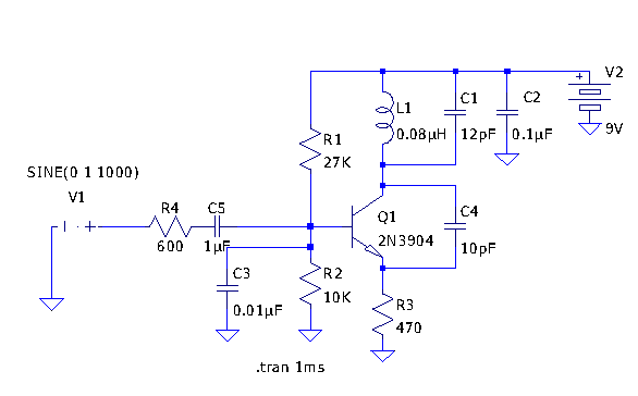
The gold detector circuit operates on the principle of electromagnetic induction, where an oscillating current generates a magnetic field that interacts with conductive materials, such as gold or other metals. The circuit consists of a basic oscillator circuit, which can be implemented using a transistor or an operational amplifier. The frequency of oscillation is set around 140 kHz, which is suitable for detecting small metallic objects.
To construct the PCB, a layout is created using PCB design software, such as Eagle. The layout includes traces for power, ground, and signal paths, as well as pads for component placement. After printing the design onto glossy paper with a laser printer, it is carefully aligned and adhered to the copper-clad PCB. The application of heat from a hot iron plate transfers the toner from the paper onto the copper surface, creating a resist pattern for the etching process.
Once the PCB is prepared, it undergoes an etching process to remove the unprotected copper, leaving behind the desired circuit traces. This can be done using an etching solution such as ferric chloride. After etching, the board is cleaned, and components such as resistors, capacitors, and the oscillator circuit elements are soldered onto the PCB according to the layout.
The final assembly includes tuning the AM radio receiver to the specific frequency of the oscillator to detect the harmonic signal. This allows the user to identify the presence of gold or other metals within the detection range. The design and construction of this gold detector circuit provide a practical application of basic electronic principles and PCB design techniques.Here the very simple and easy build gold detector circuit. The circuit capable to sense gold or metal or coins from a distance of about 20cm, depending on the size of the object to detect. The circuit oscillates at about 140kHz and a harmonic of this frequency is detected by an AM radio. You can simply tune the radio receiver until a squeal is det ected. Make a PCB in very easy steps. ! Create your PCB design using PCB designer software like Eagle, print out your design on photo paper or glossy paper with laserjet printer. Stick the printed design on the PCB (copper side) and then heat it using hot iron plate. The ink will stick on the PCB and it will be ready for etching process. Note: If you don`t have laserjet printer, then you can print the design on standard paper. Copy the printed design at Copy Service around your location (with glossy paper). 🔗 External reference
Related Circuits
This circuit responds to the presence of any conductive object, including humans. It does not detect object movement but can function as a proximity sensor. The circuit operates on the principle of capacitive sensing, utilizing a capacitor to detect changes...
Tetsuo Kogawa's circuit is well documented, although not in a conventional schematic form. It has been entered into LTSpice for analysis, and the schematic is presented online with some comments. The circuit includes a small air variable capacitor (C1)...
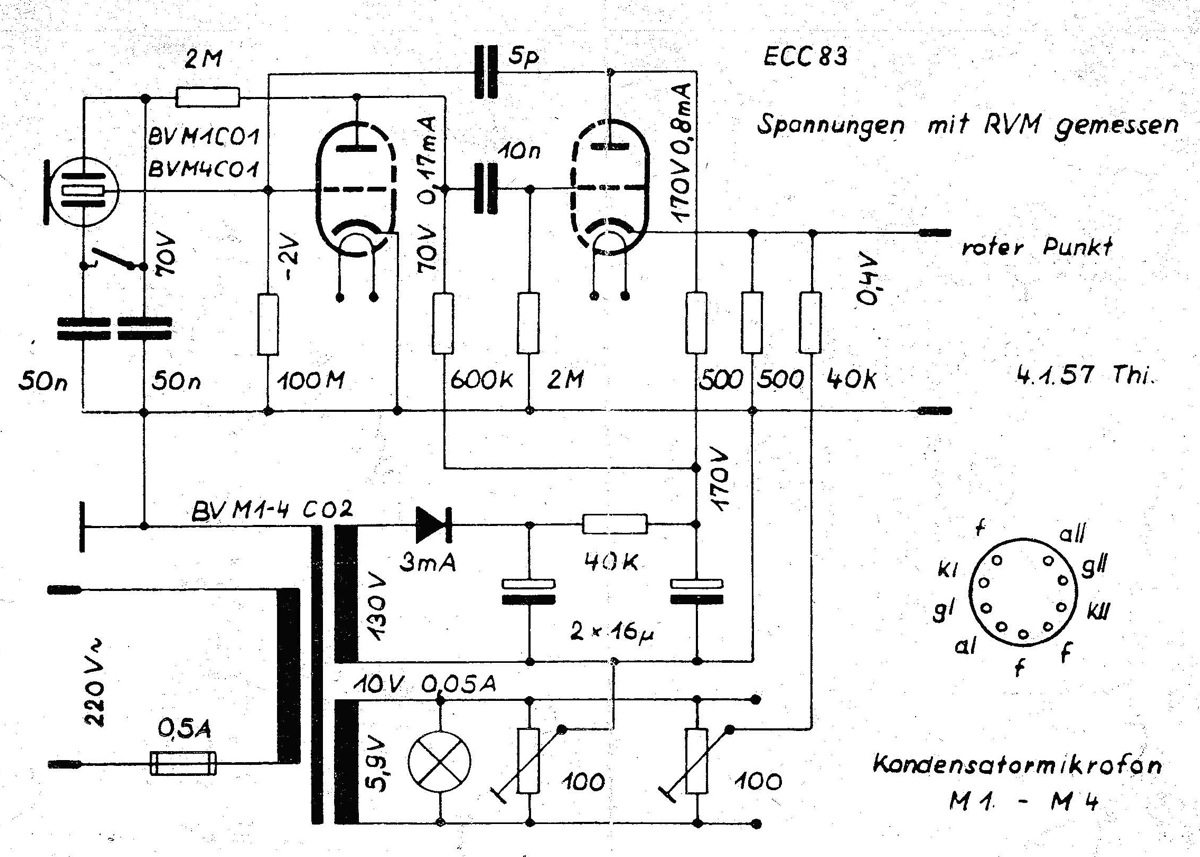
The power supply is integrated into the base of the microphone, which may cause hum issues, even with the onboard potentiometer designed to nullify this effect. Consequently, the microphone features two cables: one for power and another for audio...

An attenuator is positioned at the output of the MAX4467 voice amplifier, allowing for gains below unity. Currently, the MAX4467 operates at a gain of Av=5, which is reduced to approximately one-fifth by the attenuator, resulting in an overall...
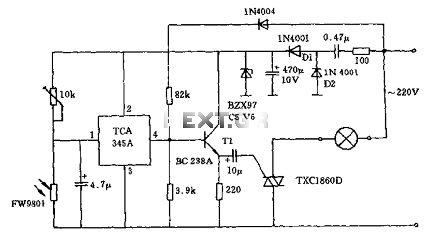
A 200W lamp switch control operates at a power supply voltage of 220V. It automatically turns the light on or off based on ambient illumination levels, specifically activating at approximately 100 lux. In low light conditions, a time-sensitive resistor...
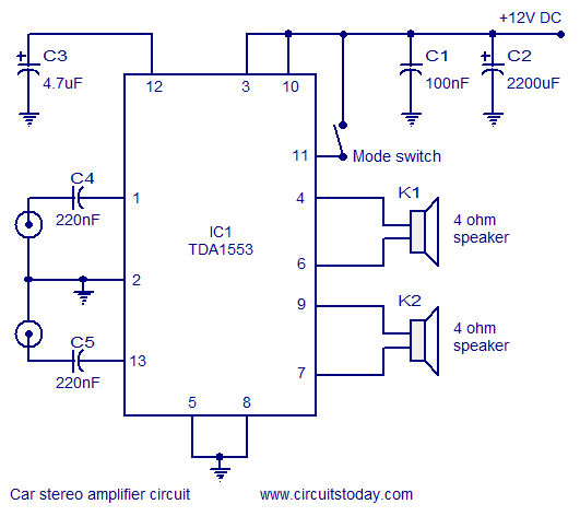
A car stereo amplifier circuit that can be used in automobiles, designed using the Class-B audio amplifier TDA1553, complete with a circuit diagram and schematics. The car stereo amplifier circuit utilizes the TDA1553, a Class-B audio amplifier known for its...