
Car Stereo Amplifier Diagram and Schematics using TDA1553 IC
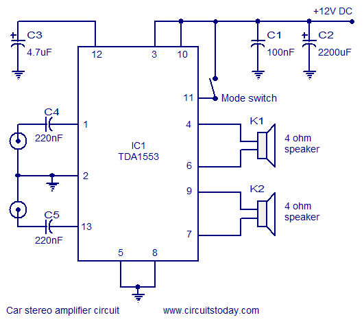
The car stereo amplifier circuit utilizes the TDA1553, a Class-B audio amplifier known for its efficiency and performance in automotive applications. This integrated circuit is designed to deliver high-quality audio output while minimizing power consumption, making it suitable for use in vehicles where space and energy efficiency are critical.
The TDA1553 can typically provide an output power of up to 2 x 22W at a load of 4 ohms, which is ideal for driving car speakers. The circuit configuration generally includes input capacitors to block any DC offset from the audio source, ensuring that only the AC audio signal is amplified. Feedback resistors are employed to set the gain of the amplifier, allowing for customization based on the specific requirements of the application.
Power supply decoupling capacitors are essential for stabilizing the voltage supplied to the amplifier, minimizing noise and distortion in the audio output. Additionally, the circuit may incorporate thermal protection features to prevent overheating, ensuring reliable operation over extended periods.
The schematic representation of the amplifier circuit typically includes connections for input, output, and power supply, clearly indicating the placement of each component. The layout should be designed to minimize interference and optimize signal integrity, with careful attention paid to the routing of power and ground traces.
Overall, the TDA1553-based car stereo amplifier circuit is a robust solution for automotive audio systems, providing excellent sound quality and efficiency while being easy to implement with standard electronic components.A car stereo amplifier circuit that can be used in automobiles, designed using Class-B audio amplifier TDA1553, with circuit diagram and schematics.. 🔗 External reference
Related Circuits
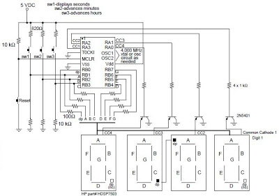
A digital clock project utilizing the PIC16C54 microcontroller can be constructed using the provided circuit diagram. This electronic project features a straightforward time-of-day clock that includes four seven-segment LED displays and three input switches, along with an additional reset...
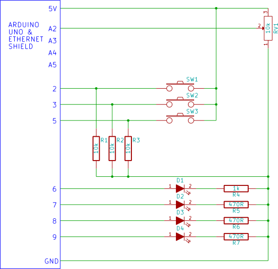
Input and output (I/O) on the Arduino web server using the SD card. Arduino inputs (analog inputs, switches) are displayed on a web page. Arduino outputs (LEDs) are controlled from a web page. Uses Ajax for flicker-free loading. The described...
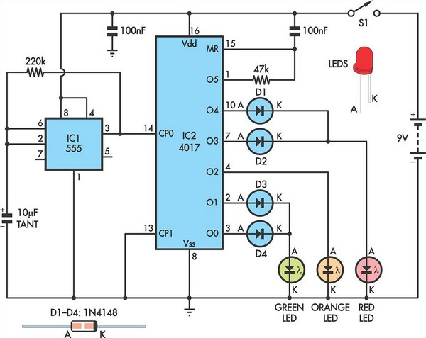
Children today often possess a wide array of toys available in stores. For those with a son or grandson who has a collection of toy cars, a handmade gift such as a set of traffic lights would be greatly...
Using this low cost project, one can reproduce audio from a TV without disturbing anyone. It does not use any wire between the TV and headphones. Instead of a pair of wires, it uses invisible infrared light to transmit...
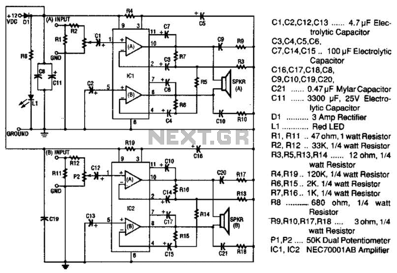
The 20-W + 20-W stereo amplifier consists of two complete, separate 20-W RMS bridge-type amplifiers. The input signal source is brought into the amplifier through a voltage divider network, which is composed of resistors R1, R2, and potentiometer P1....
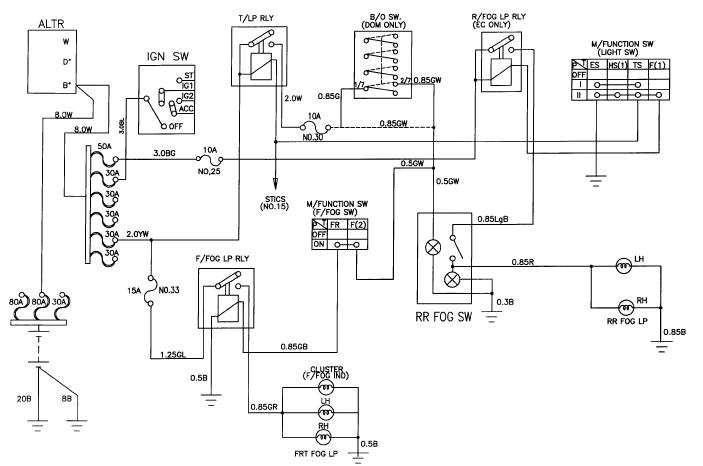
The schematic for the front and rear fog lamps of the Daewoo Korando is illustrated in the accompanying figure. It details the connections and wiring between various components of the fog lamp system, including the alternator, ignition switch, taillamp...