
Microphones schematics and documents

The integration of the power supply within the microphone's base is a design choice that can introduce unwanted hum, particularly in environments with significant electromagnetic interference. The use of an onboard potentiometer serves as a nulling mechanism to mitigate this issue, allowing for some degree of adjustment to the signal path. The dual-cable configuration—one dedicated to power and the other to audio—ensures that the audio signal remains separate from the power supply, reducing the risk of interference.
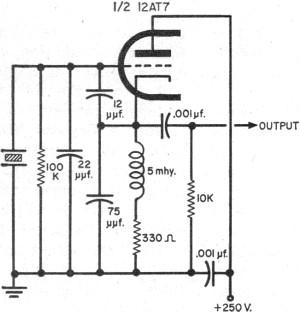
Both the M1 and M4 microphones feature a two-stage head amplifier circuit utilizing the ECC83 tube, known for its low noise and high gain characteristics. This choice of amplification technology is critical for achieving the desired audio fidelity, particularly in professional audio applications. The unbalanced output configuration, while simpler, may limit the microphone's performance in longer cable runs due to susceptibility to noise and signal degradation.
In contrast, the M5 microphone is designed for studio applications, emphasizing balanced low impedance operation. The inclusion of an external power supply and output transformer enhances its performance by providing a more stable power source and enabling balanced audio output, which is less prone to interference over long distances. The absence of a factory schematic for the M5 model necessitates reliance on hand-drawn schematics derived from physical specimens, which may introduce variability in circuit design. This further emphasizes the importance of careful analysis and documentation when working with vintage or less common audio equipment.The power supply was built into the base of the mic which can lead to hum issues despite the on-board potentiometer that acts as a `null`. This also means that the mic has two cables running from it - one for power and one for audio. Both mics use two-stage head amplifiers based around an ECC83 tube, and both have unbalanced outputs.
Here are the official schematics for the M1 and M4 mics. The M5 seems to have been the `Studio` version, with an external power supply and output transformer for balanced low impedance operation. I haven`t seen a factory schematic for the M5, but this is a drawing that I traced out from a specimen on the bench.
🔗 External reference
Related Circuits
The fundamentals of crystals have not changed since this article appeared in a 1960 edition of Popular Electronics. The methods for growing, cutting, and packaging crystals have evolved significantly. Understanding their operation at the atomic level has also advanced...
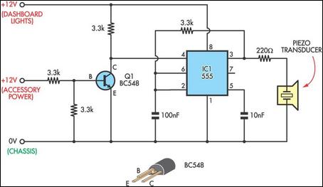
With the storm season recently upon us, it is common to switch car headlights on during the daytime. Unfortunately, it is easy to forget to turn them off again when parking, resulting in a flat battery. This circuit will...
The circuit automatically powers down a computer after Windows has been shut down, preventing users from forgetting to turn off their machines. Upon shutting down Windows, a click occurs after one second, disconnecting the PC from the mains supply....
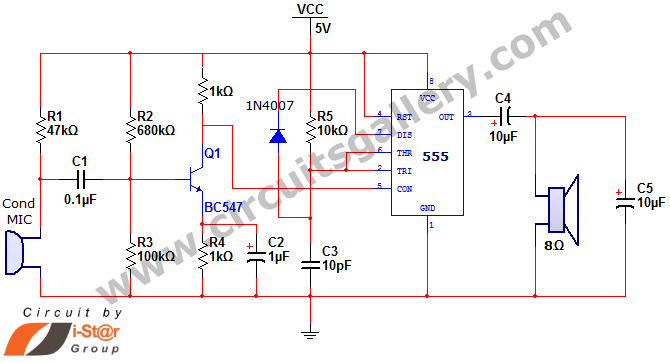
This document discusses a simple project utilizing the 555 timer IC. The 555 timer IC can be configured as an audio amplifier using an astable multivibrator configuration. It performs pulse width modulation (PWM) on an audio signal. The current...
An FM amplifier is utilized to amplify signals from an exciter in broadcast radio stations. This RF FM amplifier employs solid-state materials with a minimum gain of 9 dB. The input requirement for the FM amplifier is between 5...
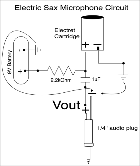
A condenser microphone (electret type with two terminals) is to be powered. A resistor of 1 kΩ and a capacitor of 10 µF have been connected to its positive terminal, while the other terminal is grounded. To power an electret...