
Gray Tube Replication 5
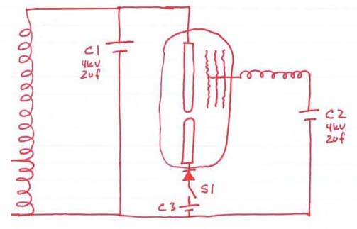
The described circuit involves a high-voltage spark gap generator, which is essential for facilitating the avalanche effect and generating a significant number of free electrons. The spark gap is designed to create a very short discharge, allowing for the emission of both transverse and longitudinal electromagnetic waves. The circuit includes a low-voltage rod, which acts as a cathode, and a high-voltage anode, where the free electrons are absorbed and subsequently bound, releasing electromagnetic radiation.
In this configuration, the capacitor C2 plays a crucial role in energy transfer. The design must ensure that the spark gap remains at an optimal distance to maintain the necessary conditions for the avalanche effect without transitioning into an arc, which would disrupt the desired operation. The grids are positioned to capture the emitted waves and convert the energy into usable power for the load. The diode placement is critical in controlling the direction of current flow and ensuring that the energy harvested from the spark gap is effectively utilized.
The circuit should incorporate feedback mechanisms to monitor the voltage and current levels, allowing for adjustments to maintain optimal performance. Additionally, the use of high-frequency components may be necessary to handle the rapid changes in voltage and current associated with the spark generation and the subsequent energy transfer process.
Overall, the successful implementation of this circuit relies on a thorough understanding of the principles of electromagnetic radiation, electron behavior in high-voltage environments, and the intricate balance between spark generation and energy harvesting.This was not simply shorting out a cap thru the coil. Or thru the tube for that matter. However, I think you are wrong in how the tube works. There is not supposed to be a discharge from the low voltage rod to C2. How could you gain any energy by just having electrons you already had jump over a spark gap into a cap That idea just doesn`t cut it! What`s more, that`s also totally inconsistent with the observation in McKays file ( ) where they observe more power with increasing resistance at the low-voltage rod. I think the only logical explanation of what is going on is that a ver very *short* spark emits radio-waves, both normal transversal waves as well as *longitudinal* waves, across a wide spectrum running well into the 10s of Ghz, at least 60 GHz, judging by Bose`s experiments with micro-waves ( J.
C. Bose: 60 GHz in the 1890s ). In an article about Loeb and Meeks `The Mechanism of The Electric Spark` ( The mechanism of the electric spark and its possible role in tapping Radiant Energy ), you can find the following: "When the free electrons are absorbed by the high voltage anode the free electrons become bound again, and give up a quanta of electromagnetic radiation. Because of the huge increase in free electrons developed in avalanche the amount of EMR given off by the high voltage anode is in the range of hundred to thousand fold increase.
Thus the huge "Radiant Event". [. ] When Mark [Mckay] and I were first doing research on the Gray Circuit we (especially he) kept blowing up components. It was a year before I read the rare book by Loeb and Meek that explained why the components were blowing up.
There was a current gain of 500% with the open air, high voltage spark gap. " "If Loeb and Meek are correct then if we assume a spark gap of 3 mm and a voltage of 5, 000 volts there are roughly 2, 000 electrons created by avalanche for every one electron leaving the cathode. They state that most of these `free electrons` are absorbed by the anode. [. ] In conclusion: Sparks and Arcs are two different beast. My initial research into the amperage necessary to form an arc does not apply to spark and the process of avalanche where this huge gain mechanism is possible.
" So, here it is clearly said that you want just a *spark* and not an *arc*, because you want the process of avalanche to occur, which I think should be attributed to longitudinal waves bouncing back and forth between the rod and grids. The reason for that is that Tesla`s wireless power transmission system could only have worked if he used longitudinal waves *and* if these tap of ZPE and strenghten themselves.
Otherwise, you can never transmit a decent amount of power trough the air without a focussed beam. Since Tesla used spheres mounted as high as possible, he definately did not use anything even close to focussed beam, and therefore the (longitudunal) waves he used must somehow have tapped ZPE, most likely by kicking positron-electron pairs floating around in the vacuum to such an extent that they separate and become free charge particles, adding additional force to the shock wave. Just about everyone, including myself, seems to have believed C1 is discharged into the tube and this causes an outward event that is captured by the grids and that powers the load.
This is evidently NOT the case. It is the inverse. John showed electron movement from rods to grids so he knew all along exactly how it worked or what can be taken from his drawings at least that it was C2 that was powering the load. As it was mentioned, the patent does say that but nobody is doing what the patent says. The "choices" that seem to be of debate were primarily with the diode placement. Was Gray wrong and Bedini right Bedini has it right and I still have reason to believe this. The grids are the standing potential of C2 until LV rod is swi 🔗 External reference
Related Circuits
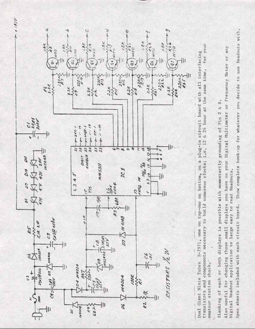
A Burroughs B-7971 Nixie Tube clock was constructed in 1979 during the senior year of high school. The digits measure 2.5 inches in height, enabling visibility from anywhere in the bedroom without the need for glasses. The clock circuit...
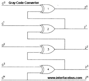
Gray Code is a positional binary number notation where any two numbers differing by one are represented by expressions that are identical except in one position, differing by only a single unit in that place. This code consists of...
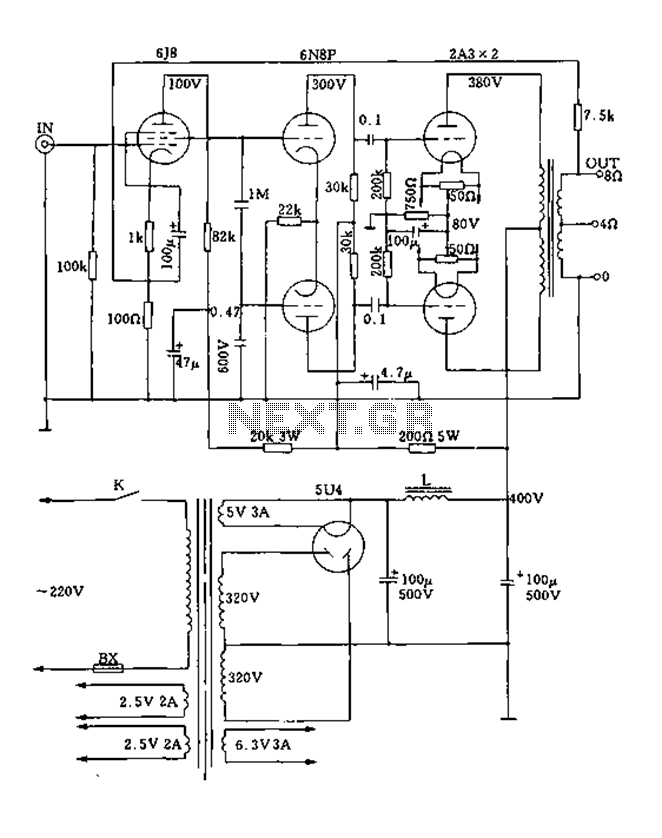
FIG. 2A3A is a low direct thermal resistance transistor with a resistance of only 800 ohms. The output transformer has a primary screen to load impedance of 3.5k ohms. The push-pull amplifier tube operates with a screen voltage ranging...
This revision reduced the signal level and treble response in the preamp for a smoother sound in both cathode and fixed bias modes. The power supply was also revised for lower B+ voltages to the EL84 plates. This amp...
The diode tube under examination is essentially Edison’s early incandescent bulb containing a plate. The term "diode" refers to the two elements or electrodes within the glass container that constitute the tube. Shortly after the discovery of the Edison...
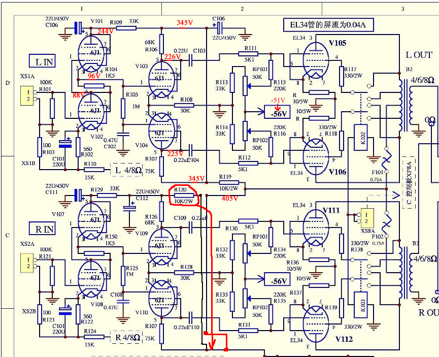
The only schematic of this amplifier known is the one obtained from Song at Canadian HiFi Online. The schematic in question represents the electronic configuration of a specific amplifier model. This schematic is crucial for understanding the circuit's operation, including...