
Trainwreck Blues tube amplifier for Guitars

The described circuit modification focuses on enhancing the tonal quality and operational flexibility of a guitar amplifier, specifically the Blues Express amp. The preamplifier stage has been adjusted to achieve a smoother sound profile, which is critical for applications where tonal clarity and warmth are desired. The reduction in treble response is particularly beneficial for players seeking a more vintage or mellow tone.
The power supply alterations, particularly the adjustment of B+ voltages to the EL84 output tubes, are essential for optimizing the performance of the amplifier under varying load conditions. The implementation of a crossline RC network (150k/1200pF) serves to effectively manage AC voltage levels on the EL84 grids, reducing harsh high frequencies and contributing to a more balanced output.
In this design, zener diodes across the EL84 grid stoppers provide an additional layer of protection against excessive AC voltage, ensuring reliable operation. The optional 100pF capacitors across the 100k resistors introduce a low-pass filter effect that dynamically responds to signal levels, further enhancing the amplifier's tonal versatility.
The modifications also include a DPDT switch that allows users to toggle between different grid load resistor values (56k, 82k, and 45k), enabling distinct tonal characteristics for various musical styles. The switchable conjunctive filter simplifies the circuit by eliminating the need for additional capacitors across the plate resistors, thereby streamlining the design while maintaining sonic integrity.
The feedback loop introduced by the Smooth switch creates a unique tonal effect by allowing for local feedback between the plate and grid of the 2nd stage. The choice between traditional and alternate feedback resistor values (22M and 44M) allows for customization of the amplifier's response, catering to the preferences of different players.
Overall, these enhancements culminate in a refined amplifier design that balances flexibility and sound quality, making it suitable for a wide range of musical applications.This revision reduced the signal level and treble response in the preamp for a smoother sound in both cathode and fixed bias modes. The power supply was also revised for lower B+ voltages to the EL84 plates. "This amp was built on the chassis of an Electar Tube 30 amp, which is advertised as a 20 watt Class A amp.
This variation uses a crossline 150k/1200pF RC network after the PI coupling caps to reduce the AC voltage on the EL84 grids and to cut some of the highs. This variation uses zeners across the EL84 grid stoppers to limit the AC voltage on the grids. The optional 100pF caps across the 100k * resistors add an LPF effect triggered by the signal level.
This is the final version of the Blues Express amp. The zener limiting circuit was removed and a modified cross-line MV was installed in its place. The bias/grid load resistors were returned to their original value of 220k. The 2nd stage supply was rewired to B+5 instead of B+4 and the 0.22uF/630v poly cap from B+5 to ground was drawn in. A center-off DPDT switch was used to toggle the grid load of the 3rd stage from 56k to 82k in the two "blues" modes, while dropping to 45k to cut the gain a bit in the "Fat" mode.
The switchable conjunctive filter was used to smooth out the response of the amp, making the 250pF caps across the 2nd and 3rd plate resistors unnecessary. With the .022uF and .033uF caps in series the net capacitance is .0132uF. The Smooth switch is a local feedback loop between the plate and grid of the 2nd stage. The traditional value of 22M allows for a compressed sound while the alternate value of 44M has a more subtle effect.
🔗 External reference
Related Circuits
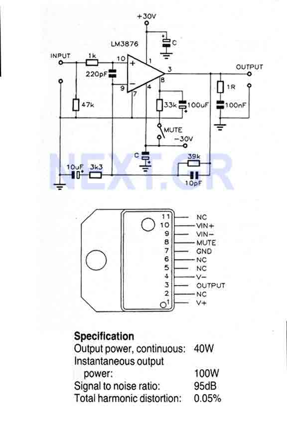
This Circuit is based on the LM3876. A 11-pin plastic package IC with high performance audio power amplifier, an output mute function which can be used to eliminate switch-on and switch-off "thumps" to the loudspeaker load. It is capable...
A charge amplifier is an amplifier whose equivalent input impedance is a capacitive reactance that is very high at low frequencies. Thus, contrary to what its name may suggest, a charge amplifier does not amplify the electric charge present...
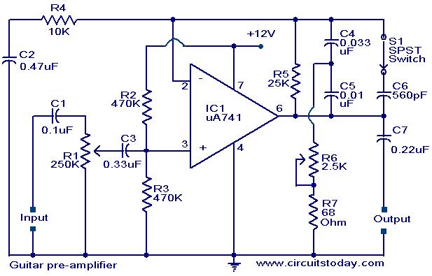
A preamplifier circuit designed for high-impedance electric guitar pickups is presented. This circuit utilizes a uA 741 operational amplifier (IC1) configured as a non-inverting amplifier. The potentiometer R1 functions as a volume control, while potentiometer R6 serves as a...
R1_47K 1/4W Resistor, R2_4K7 1/4W Resistor, R3_22K 1/4W Resistor, R4_1K 1/4W Resistor, R5, R12, R13_330R 1/4W Resistors, R6_1K5 1/4W Resistor, R7_15K 1/4W Resistor, R8_33K 1/4W Resistor, R9_150K 1/4W Resistor, R10_500R 1/2W Trimmer Cermet, R11_39R 1/4W Resistor, R14, R15_R33 2.5W...
The input impedance can be classified into high-impedance and low-impedance inputs based on the requirements of various audio equipment and the load impedance. High-impedance input mode is typically utilized in general audio devices such as CD players, VCD players,...
There is a modification to the RC delay circuits that some may want to consider. If a shorter discharge time is desired, this modification enables the circuit to restart more quickly. The modification to the RC delay circuit involves adjusting...