
Grid Dip Oscillator (GDO) Instrument
 Instrument")
The grid dip oscillator (GDO) circuit is an essential tool for RF engineers and hobbyists, enabling the measurement of resonant frequencies in various circuits. The design features a range of seven plug-in coils, each tailored for specific frequency bands between 3.0 MHz and 30 MHz. This versatility allows users to explore a wide spectrum of radio frequencies with ease.
The connection to a frequency meter via coaxial socket J2 enables accurate frequency readings, enhancing the functionality of the GDO. The inclusion of TR2 as a DC amplifier is crucial; it amplifies the output signal, making it suitable for driving a 1 mA FSD meter. The sensitivity control provided by resistor R7 ensures that the meter can be calibrated to display accurate readings across different signal strengths.
In addition to its primary function, the circuit can also operate as a field strength meter or RF sniffer when TR1 is deactivated using switch S2. This feature allows users to measure the strength of RF signals in the vicinity, providing valuable insights during troubleshooting or experimentation.
The coils used in this circuit are constructed on Teflon formers, which offer excellent dielectric properties and stability. The design incorporates two female sockets that securely connect to male sockets on the main instrument, ensuring reliable coil swapping and ease of use.
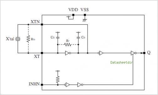
Overall, this grid dip oscillator circuit exemplifies a well-engineered solution for frequency measurement and RF signal analysis, making it a valuable addition to any electronics laboratory or workshop.This is a grid dip oscillator (GDO) circuit developed by Luigi Falcone. This circuit uses seven plug in coils covering 3. 0 to 30Mhz. This circuit can be connected to the a frequency meter by using The coaxial socket J2. The figure below shows the schematic diagram of the circuit and the coil information: DC amplifier is formed by TR2 that permit the use of a 1mA FSD meter. R7 is used to control the sensitivity of 1mA FSD meter. a field strength meter/RF sniffer is formed by the instrument with TR1 switched off (via S2). The coils are wound on Teflon formers with two female sockets which plug-in to two male sockets on the instrument. [Source: qsl. net] We aim to transmit more information by carrying articles. Please send us an E-mail to wanghuali@hqew. net within 15 days if we are involved in the problems of article content, copyright or other problems.
We will delete it soon. 🔗 External reference
Related Circuits
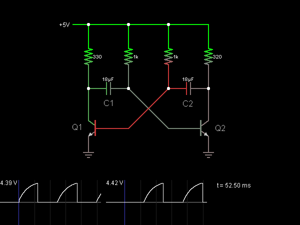
This circuit functions as an astable multivibrator, also known as an oscillator. The two transistors are interconnected in a manner that allows the circuit to alternate between two states. In one state, the base of transistor Q1 is approximately...
Online Electronics Course covering the Science of Radio Frequency Engineering, including topics such as Electronics, Microwave Technology, Waveguides, Antennas, Tubes, Historical Context, Klystrons, Magnetrons, Traveling Wave Tubes (TWT), Internet of Things (IoT), Klystrodes, Broadcast Equipment, and Repair Techniques. The online...
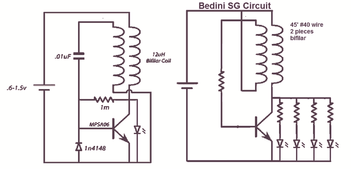
It would be beneficial to obtain schematics of the Joule Thief and Bedini oscillator circuit connections. This is an area that has not been previously explored. The schematic on the left was sourced from the Energetic Forum, while the...
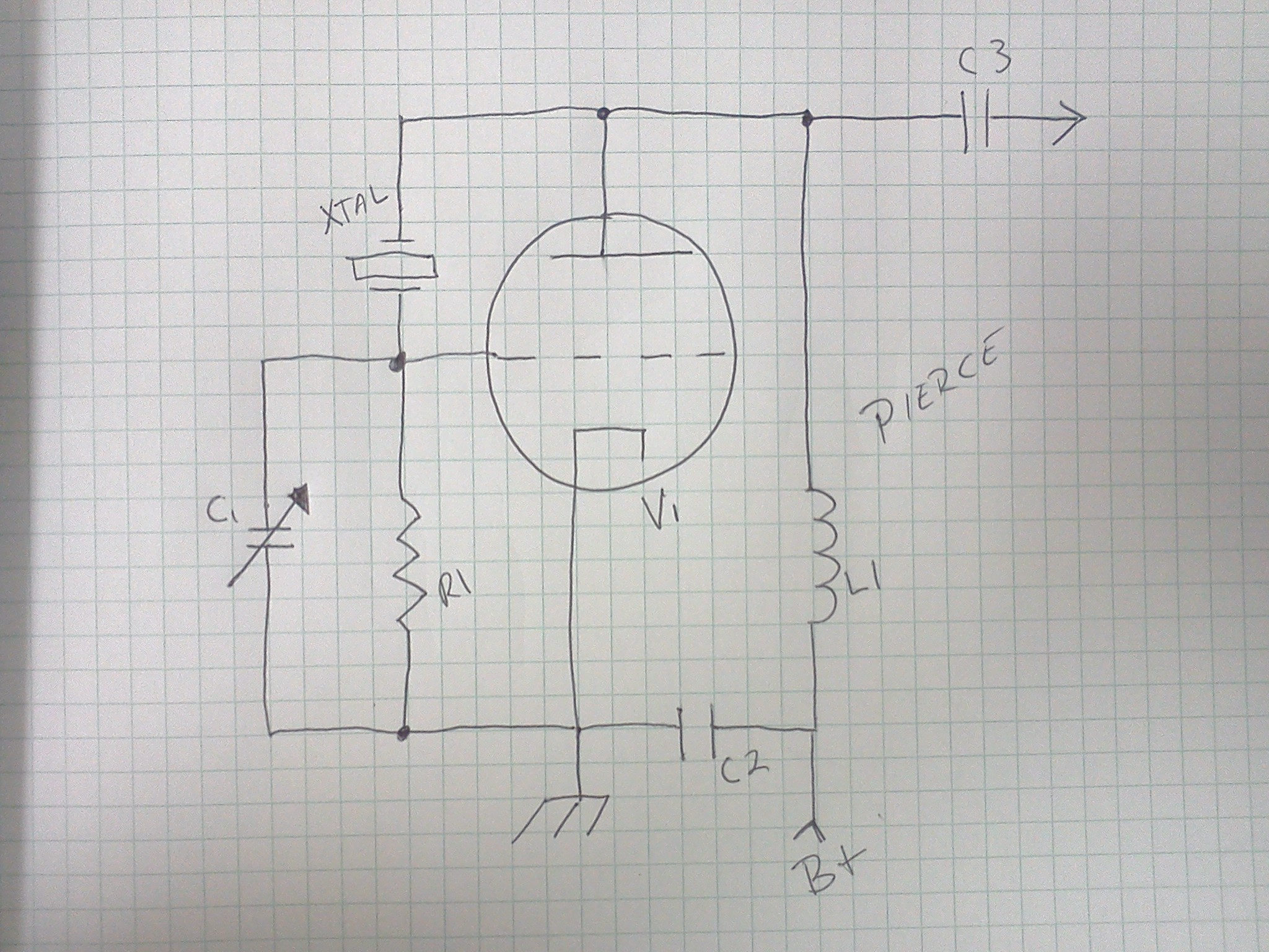
A common-base Colpitts oscillator utilizes a PNP transistor as the amplifying component. In this configuration, regenerative feedback is sourced from the tank circuit and directed to the emitter. The base bias is supplied by resistors RB and RF, while...
This CMOS square-wave oscillator utilizes the 4047 multivibrator circuit, suitable for both monostable (one-shot) and astable applications. In the provided configuration, the 4047 operates as an astable multivibrator. The circuit features three outputs from the 4047, with the first...
The CF8223A is an FSK (Frequency Shift Keying) decoder and DTMF (Dual Tone Multi-Frequency) receiver integrated circuit (IC). It is manufactured using a CMOS process and includes a power-down feature for low power dissipation operation. The FSK decoder and...