
Astable Multivibrator (Oscillator)
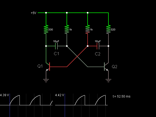
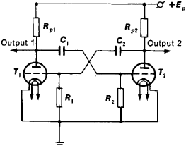
The astable multivibrator circuit described operates continuously, producing a square wave output without requiring any external triggering. The primary components involved are two NPN transistors (Q1 and Q2), two capacitors (C1 and C2), and resistors that set the timing characteristics of the oscillation.
In a typical configuration, resistors R1 and R2 are connected to the base of each transistor to limit the base current and establish the switching thresholds. The capacitors C1 and C2 are responsible for timing the transitions between the two states. When Q1 is active, it charges C1, and as C1 reaches a certain voltage, it triggers Q2, which then pulls the base of Q1 low, causing it to turn off. This feedback loop creates a continuous oscillation.
The frequency of oscillation can be calculated using the values of the resistors and capacitors in the circuit. The formula for the frequency (f) is given by:
f = 1 / (ln(2) * (R1 + R2) * C1)
This equation highlights the relationship between the resistor and capacitor values and the frequency of the output waveform. The duty cycle of the output can also be adjusted by varying the resistor values, allowing for customization of the output signal characteristics.
The output of the circuit can be taken from the collector of either transistor, providing a square wave signal that can be used for various applications, including clock pulses for digital circuits, tone generation, or as a basic timer. Overall, the astable multivibrator is a fundamental building block in electronic design, illustrating the principles of feedback and oscillation in transistor-based circuits.This circuit is an astable multivibrator, or oscillator. The two transistors are cross-coupled in such a way that the circuit switches back and forth between two states. In one state, the base of Q1 is about one diode drop above ground, allowing a base current to flow. This keeps Q1 switched on, in saturation mode, allowing a current to flow throu gh the collector, keeping Q1`s collector voltage low, and discharging C1. Q2 is switched off, because its base voltage is not high enough to switch it on. As the collector current into Q1 charges C1, the base voltage for Q2 goes up, until it is high enough to switch on Q2, causing a current to flow through its collector, which drops the collector voltage (the current causes a voltage drop across the resistor above it). The right side of C2 has dropped, but the voltage across it hasn`t changed, so this causes Q1`s base voltage to drop below ground, switching it off.
🔗 External reference
Related Circuits
A variable frequency, variably duty cycle 555 configuration is set up in astable mode. A set of potentiometers is utilized to achieve a wide range of control. The output is functioning well; however, there is an issue. The circuit...
The circuit below is a one-shot multivibrator, also referred to as a monostable multivibrator or timer. The primary function of this circuit is to generate a single output pulse in response to an input trigger. The one-shot multivibrator is a...
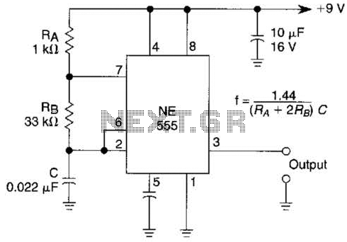
An astable multivibrator based on the 555 timer is presented. The frequency is approximately 975 Hz, determined by the values of RB and C. The astable multivibrator configuration using the 555 timer is a popular circuit for generating square wave...

The 555 timer integrated circuit (IC) is an exceptionally versatile component utilized in various applications, including generating clock pulses, switch debouncing, and functioning as an output transducer. The standard 555 IC is packaged in an 8-pin configuration, available in...
A relaxation oscillator utilizes two tubes, transistors, or other electronic devices, with the output of each connected to the input of the other through resistance-capacitance elements or other components to achieve in-phase feedback voltage. This electronic circuit employs positive...
The NE555 can be used to construct an astable multivibrator or blinker. It is important to understand the necessary components and considerations involved in this process. The NE555 timer IC is a versatile device commonly used in various timing, pulse...