
Ground pole & 2-Half-Wave Dipole Antenna
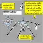
The described antenna system is a versatile design commonly utilized in various communication applications, particularly in mobile and portable setups. The Ground Pole Antenna (GPA) functions effectively by leveraging the vehicle's body as a ground plane, enhancing the antenna's performance by improving radiation efficiency and reducing signal loss.
The GPA is designed to operate with a 50-ohm impedance, making it suitable for most professional RF equipment, such as transmitters found in police vehicles. Its power output is superior to that of a Half-Wave Dipole Antenna, which typically operates at a 75-ohm impedance. The choice of impedance is crucial as it affects the antenna's matching with the transmitter, ensuring maximum power transfer and minimal reflection.
For construction, the antenna consists of two aluminum rods, each of a specified length "L" in meters. The length of these rods is critical for determining the operational frequency of the antenna. The rods are connected at a center point, which can be adjusted to achieve the desired resonance. The use of aluminum is advantageous due to its lightweight and corrosion-resistant properties, which contribute to the durability and longevity of the antenna in outdoor environments.
When deploying this antenna, it is essential to ensure that it is mounted securely and positioned to maximize signal reception and transmission. The performance can be further optimized by adjusting the length of the rods and the angle at which they are mounted. This antenna design is particularly useful in scenarios where a Ground Pole Antenna is not available, providing a reliable alternative for communication needs.This Antenna is most widely used all over the world. For example, when you see a police car it has a transmitter with Ground Pole Antenna The body of car serves as ground). It accepts load from 50 ohm source and has larger power output than Half-Wave Dipole Antenna. It accepts load from 75 ohm source and has much smaller power output than Ground Pole Antenna. Use this antenna only when you don`t have GP Antenna. Construction: Two aluminum rods ,each of length "L" in meters are joined together throug 🔗 External reference
Related Circuits
The circuit diagram of a TV antenna is sourced from the technical information provided by Chinaicmart. For more detailed information or additional circuit designs, further inquiry may be necessary. The circuit diagram for a TV antenna typically consists of several...
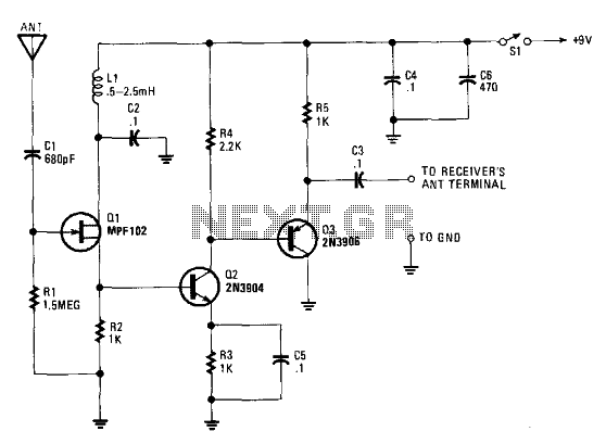
This schematic illustrates an FM, AM/MW, and SW antenna amplifier circuit, also referred to as an antenna preamplifier circuit. It is designed to enhance weak signals from FM, AM/MW, and SW bands. The circuit is straightforward and can be...
Results are displayed on an analog VSWR meter. The design was originally published in Break-In, New Zealand's amateur radio magazine in September/October 2005, and is republished here with the editor's permission. Note: Break-In is a term used in amateur...
A loop antenna is a radio antenna made up of a loop (or loops) of wire, tubing, or other electrical conductor with its ends connected to a balanced transmission line. This design includes two distinct types of antennas: the...
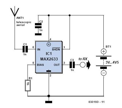
This is a high-performance radio receiver antenna amplifier designed for the entire VHF broadcast and PMR band (100-175 MHz) that can be successfully constructed without... This radio receiver antenna amplifier is engineered to enhance the signal quality and reception capabilities...
The signal booster, constructed using several transistors and supporting components, provides an RF gain ranging from approximately 12 to 18 dB across a frequency range of about 100 kHz to over 30 MHz. The RF signal is directly coupled...