
the circuit diagram of tv antenna
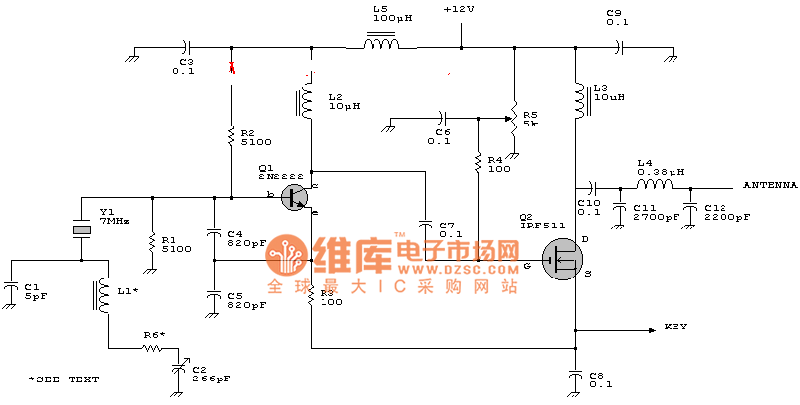
The circuit diagram for a TV antenna typically consists of several key components that work together to receive television signals effectively. The primary elements include the antenna itself, which can be either a dipole or a loop design, depending on the frequency range it is intended to capture.
The antenna is connected to a coaxial cable, which serves as the transmission line to carry the RF (radio frequency) signals to the television receiver. The coaxial cable is designed to minimize signal loss and interference, ensuring that the quality of the received signal is maintained.
In addition to the antenna and coaxial cable, a matching network may be included in the circuit to ensure that the impedance of the antenna matches that of the transmission line and the receiver. This is crucial for maximizing power transfer and minimizing reflections that could degrade the signal quality.
The circuit may also incorporate a low-noise amplifier (LNA) positioned close to the antenna. The LNA boosts the weak signals captured by the antenna before they travel through the coaxial cable, thus enhancing the overall performance of the system.
Furthermore, filters can be integrated into the design to eliminate unwanted frequencies and reduce noise, ensuring that only the desired television signals are amplified and sent to the receiver.
For optimal performance, the antenna design should be tailored to the specific frequency bands used by local television stations, taking into account factors such as gain, directivity, and bandwidth. This will ensure that the antenna can effectively receive signals from various directions and distances, depending on the geographical location and surrounding environment.
Overall, the circuit diagram of a TV antenna represents a critical component in the reception of broadcast television signals, and understanding its design can significantly improve signal quality and viewing experience.The circuit diagram of TV antenna The diagram is from the tech information of chinaicmart. IF for more detailed infomation or more circuit .. 🔗 External reference
Related Circuits
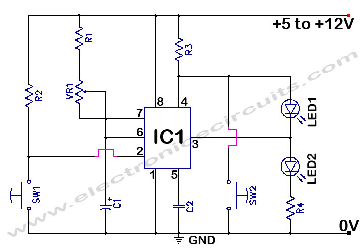
The 555 Timer Time Delay Circuit uses LEDs to visually indicate the status of the circuit at any moment. The operation begins when the reset switch, SW2, is activated. The 555 Timer is a versatile integrated circuit widely used for...
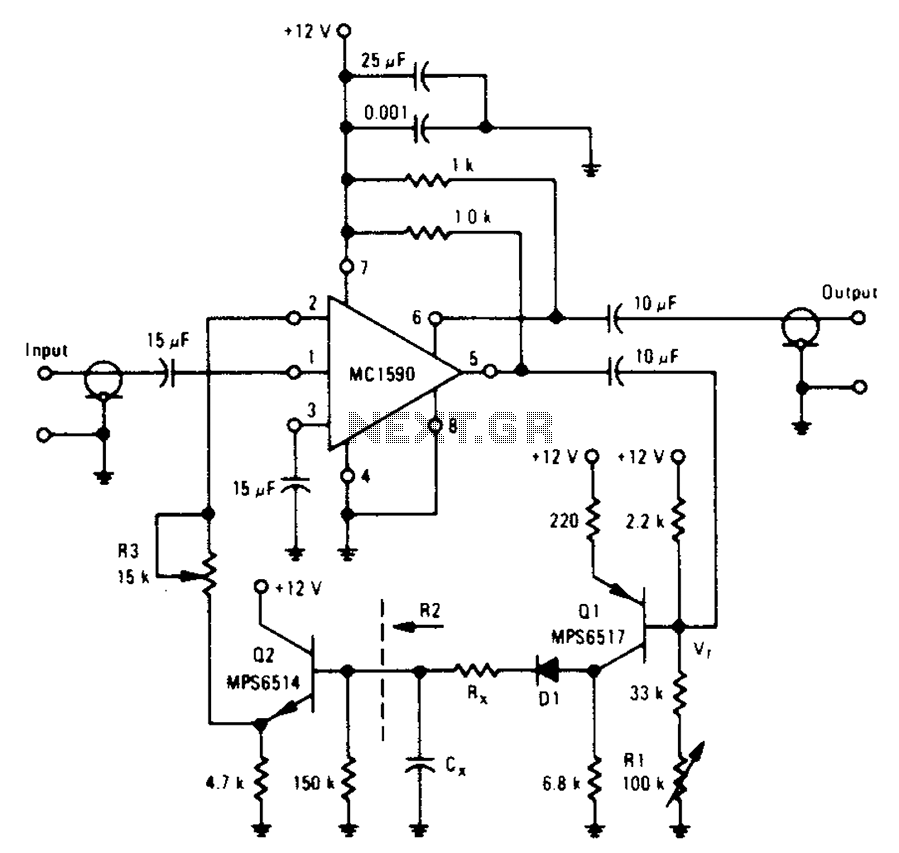
An amplifier designed to achieve a voltage gain of approximately 20, utilizing the MPS6517 PNP transistor in the emitter follower configuration. The RI controller allows for adjustment of the transistor's quiescent point. The output signal is activated only when...
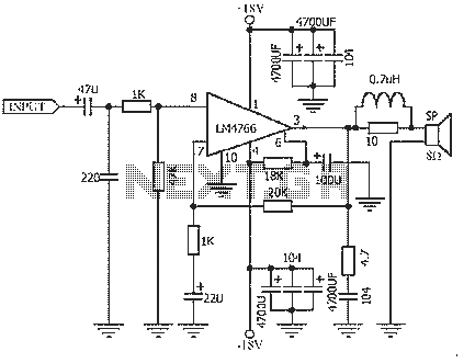
The NS LM4766, launched by a US company, is a two-channel power amplifier integrated circuit. Each channel can output an average power of 40W at an 8-ohm load, with distortion levels lower than 0.1%. It is part of National...
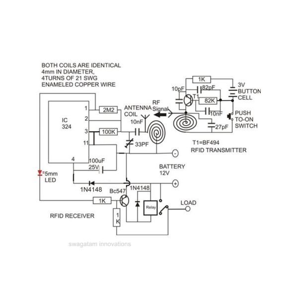
Constructing an RFID access control circuit at home and witnessing its functionality can be a remarkable experience. While the circuit may not be considered high-tech, its low cost combined with the satisfactory results achieved demonstrates a significant level of...
The loop gain of the operational amplifier (OP) is primarily influenced by the ratio of the input resistor to the feedback resistor. Consequently, any resistance error can lead to a corresponding gain error, which necessitates the use of high-precision...
The circuit depicted can be utilized to operate at a voltage of +5V for Single Board Computer (SBC) power, preventing damage caused by over-voltage from the power supply throughout the SBC. This circuit serves as a protective mechanism for Single...
Warning: include(partials/cookie-banner.php): Failed to open stream: Permission denied in /var/www/html/nextgr/view-circuit.php on line 713
Warning: include(): Failed opening 'partials/cookie-banner.php' for inclusion (include_path='.:/usr/share/php') in /var/www/html/nextgr/view-circuit.php on line 713