
Pots water alarm circuit

The flower watering indicator circuit serves as an effective solution for maintaining the health of potted plants by providing a visual cue for watering needs. The design utilizes a combination of transistors and a timer IC to monitor soil moisture levels accurately. The N-channel junction field effect transistor (VT1) acts as a switch that responds to the resistivity of the soil. When the soil is sufficiently moist, the increased resistivity prevents VT1 from conducting, allowing the circuit to activate the 555 timer.
The timing circuit, configured as a low-frequency multivibrator, produces a square wave output that drives the LEDs. The blinking of the LEDs serves as a reminder to the user to water the plants. This feature is particularly advantageous for individuals who may forget to check their plants regularly. The circuit's low power consumption ensures that it can operate for extended periods without requiring frequent battery replacements, making it practical for long-term use.
The use of insulated wires as electrodes provides a simple yet effective method for measuring soil moisture. The electrodes can be inserted into the soil at a distance that ensures accurate readings without short-circuiting. Additionally, the inclusion of a miniature switch allows for manual control over the circuit, enabling users to deactivate the system when not needed.
Overall, this flower watering indicator circuit exemplifies a practical application of electronic components to enhance plant care, combining efficiency and ease of use in a compact design.Are the flowers in pots need watering if the soil surface moist observation alone is sometimes unreliable. For this reason, the production of dry flower instructions which, whe n the pot of water, the indicator on the flares, watering the flowers to remind people to give. Flower water indicator circuit is shown. The circuit is mainly composed of a field effect transistor VT1, VT2 transistor 555 and a time base circuit, when the soil water, soil resistivity have significantly increased, then M, N great resistance between two points, N-channel junction field effect transistor gate VT1 close to the negative supply voltage, VT1 end. In this case, the base of transistor VT2 through resistor Rz, R3 get the drift, VT2 conduction. VT2 emitter potential rises 555 time base circuit. Since the time base circuit connected to an ultra-low frequency multivibrator, the oscillation frequency of about 1Hz.
When the base was a little electricity to work, the light-emitting diodes as the frequency of the low frequency oscillation signal twinkling glow red, to remind people should be given a potted plant watering. When the basin is not water, soil resistivity is very small. Equivalent to M, N have a small resistance between the gate so VT1 near-contact to close the gate voltage ov, conduction between the drain and source of the poles.
When VT1 conduction, the drain potential drop, so that VT2 deadline, which the emitter bit is also down to ground potential, time base circuit and therefore stop working, LED tube LED pull no longer shine. When the wine guide VT1, VT2 off, timebase circuit does not work, the entire circuit consumes very little about ImA.
Therefore, if the power source on the 5th battery-powered, can also be used for a long time., When used with two wire insulation stripped as two electrodes, inserting them in a pot of soil, the two electrodes separated by a few centimeters can to the. If the circuit is usually not required, as long as a series of miniature switches in the positive power supply circuit can be a negative power consumption is extremely small, very long time without changing the battery.
VTJ circuit current rating 0.5N 5mA, pinch-off voltage of about 4V. With 3DJ6E, 3DJ6F or 3DJ6G. VT2 with 3pG6 when available NE555-based circuit.
Related Circuits

A typical computer motherboard CPU power supply circuit is primarily composed of the main power supply management chip RT9241 and additional components from the power management chip RT9600. The voltage command signal from the CPU is input into the...
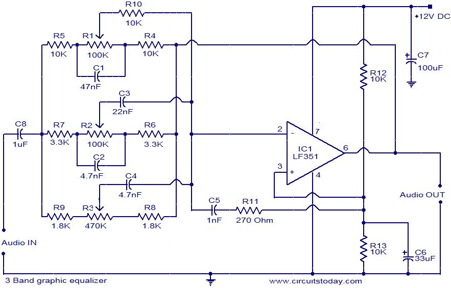
This document presents the circuit diagram of a simple three-band graphic equalizer that utilizes a single integrated circuit (IC) and a few additional components. The IC employed in this design is the LF351, which is a wide bandwidth single...

The circuit features a 24V system with a 0.5W resistor functioning as a heating element (R7), which is embedded in a sand substrate within an aquarium. The heating element is connected to 24V bulbs at both ends. The resistor...
This is a remote tester circuit designed to test TV and other remote controls. The circuit is simple and utilizes only a few components. The infrared sensor used in the circuit is the TSOP1738. When the infrared waves are...
This is the timekeeping test circuit. It includes a one-transistor circuit to switch in the 5V power supply when present and drop back to the 3V battery the rest of the time. That loop of blue wire-wrapping wire is...
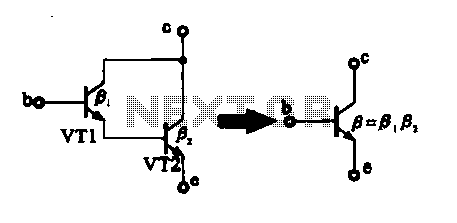
There are two composite pipe configurations: one consists of two transistors of the same type, while the other is made up of two different types of pipe configurations. The first configuration, utilizing two transistors of the same type, typically involves...