
Light Alarm Circuit with LDR

This musical light alarm circuit exemplifies a straightforward yet effective design, leveraging minimal components to create an engaging auditory alert system. The circuit's primary function hinges on the interaction between the LDR and the transistors, which work in tandem to detect light levels and activate the alarm.
The LDR serves as the core sensing element, responding to ambient light changes. Its high resistance in darkness ensures that it does not conduct electricity, keeping the circuit inactive. As light exposure increases, the LDR's resistance drops, allowing current to flow through the circuit. The adjustable 220KΩ preset resistor plays a crucial role in calibrating the sensitivity of the LDR, enabling the user to set a specific light threshold for alarm activation.
Upon reaching the preset light level, the T1 transistor is triggered, allowing current to flow to the UM66 integrated circuit. This IC is designed to generate musical tones, making it an ideal choice for alarm applications. The output from the UM66 is then amplified by the T2 transistor, which enhances the audio signal before it drives the 8Ω speaker. This amplification ensures that the sound produced is loud enough to serve its purpose as a wake-up alarm.
The design allows for flexibility in power supply; while two 1.5V batteries can be used, the use of three 1.2V NiCad or NiMH batteries is recommended for their rechargeable nature, offering an environmentally friendly and cost-effective solution. The choice of UM66T for this specific implementation provides a specific melody, but other UM66 variants can be selected based on user preference, allowing for customization of the alarm sound.
Overall, this circuit is an exemplary project for those interested in basic electronics, combining light sensing with sound generation to create a functional and enjoyable alarm system.This musical light alarm circuit is very simple, uses only 7 components, a LDR and a 3. 6 V battery or 3 x 1. 2 volts rechargeable batteries. The well-known UM66 is used as the sound generator and will give a pleasent wake up alarm. As you probably know the LDR is a light dependent resistor. Normally the resistance of an LDR is very high, sometimes as high as 1M ©, but when they are illuminated with light resistance drops dramatically. In the circuit adjust the 220K © preset to the desired sensitivity, meaning adjusting the threshold point where the alarm start singing. When there is light on the light dependent resistor the T1 transistor will start conducting and powers the UM66 musical integrated circuit.
The produced musical note will be amplified by transistor T2 and fed into the 8 © speaker. On the UM66 IC are different numbers, each number giving a different musical note (in this example we use UM66T). You may use 2 x 1. 5V batteries but 3 x 1. 2V NiCad or NiMH are better because you can recharge them. 🔗 External reference
Related Circuits

WB5LUA described GaAsFET preamplifiers for several microwave bands, which included an active bias circuit for the GaAsFET. Although newer devices have been introduced that offer improved performance, they require different bias points with varying currents and voltages. Modifying the...
The photocell photoelectric tracking circuit is configured with two identical photoelectric cells that serve as light-receiving devices. When the incident light intensity is equal, the system is able to track in a predetermined manner. If there is a slight...
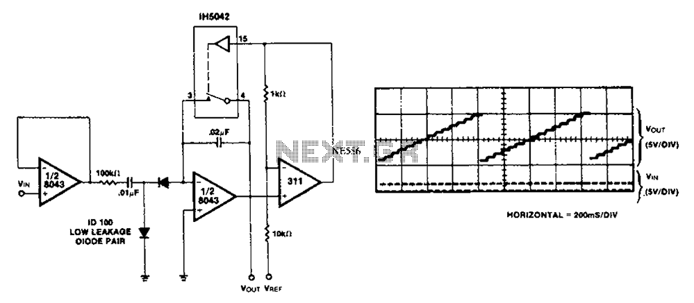
This simple circuit utilizes an LM311 as a level detector, incorporating CMOS analog switches to control capacitance. A significant feature of this counter is its ability to change numbers. The comparator operates more efficiently when there is a need...
The idea behind this snore alarm is just to rouse the snorer, not the entire household. To wake the sleeper, vibration is used, not an audible alert. The vibration is provided by a small motor housed in a small...
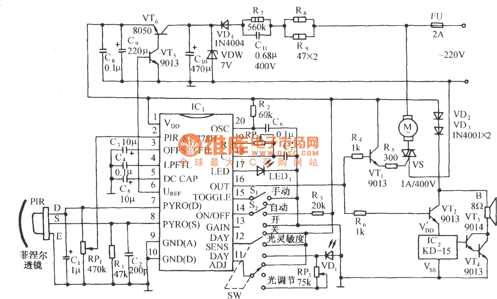
The circuit is depicted in the diagram. It is a control circuit that consists of the infrared-specific integrated circuit KC778B, which serves as the central component. Surrounding it are a pyroelectric infrared sensor head (PIR), a light control and...
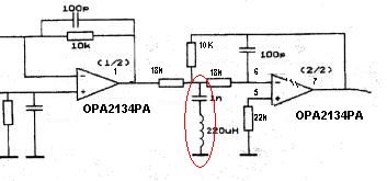
Can someone explain why there is an LC filter in the op-amp circuit? Additionally, are there any modifications that can be made to enhance the sound quality? The presence of an LC filter in an operational amplifier (op-amp) circuit serves...