
GSM/GPS Localizer with SIM908 module
The circuit design integrates several critical components to ensure efficient operation. The GSM/GPRS module, SIM908, serves as the communication backbone, allowing for data transmission and reception. The microcontroller, PIC18LF6722, orchestrates the device's functions, including processing incoming requests and managing power consumption. The inclusion of a lithium battery charger on the second board ensures that the device remains operational without external power sources, enhancing its portability and usability in various environments.
The system architecture is designed to maximize efficiency and responsiveness. The microcontroller's firmware is programmed to handle multiple scenarios, including manual position requests and automated alerts triggered by the button press. This dual functionality is essential for applications requiring immediate geographical data, such as emergency response situations. The integration of Google Maps enhances the user experience by providing a visual representation of the localizer's position.
In terms of hardware, the connection between the motherboard and daughterboard is facilitated through a connector that allows seamless communication between the microcontroller and the GSM module. The design also incorporates protective features to ensure reliable operation under varying conditions. Overall, this device represents a sophisticated blend of technology that addresses the need for precise location tracking in a compact form factor.The device is based on a GSM/GPRS module with included GPS. Its main function is to detect and communicate its own geographical position using, on the choice, the cellular phone reference system or the GPS. Its small dimensions are due to the use, for the first time, of a GSM/GPRS module integrating the GPS receiver.
That is the SIM908 a recent pr oduct by SIMCOM. The circuit of the localizer is build around two boards, one with the SIM908 on board and the second one including the microcontroller and the battery charger for the lithium battery. To get the GPS working will be necessary to complete the localizer circuit with an appropriate antenna.
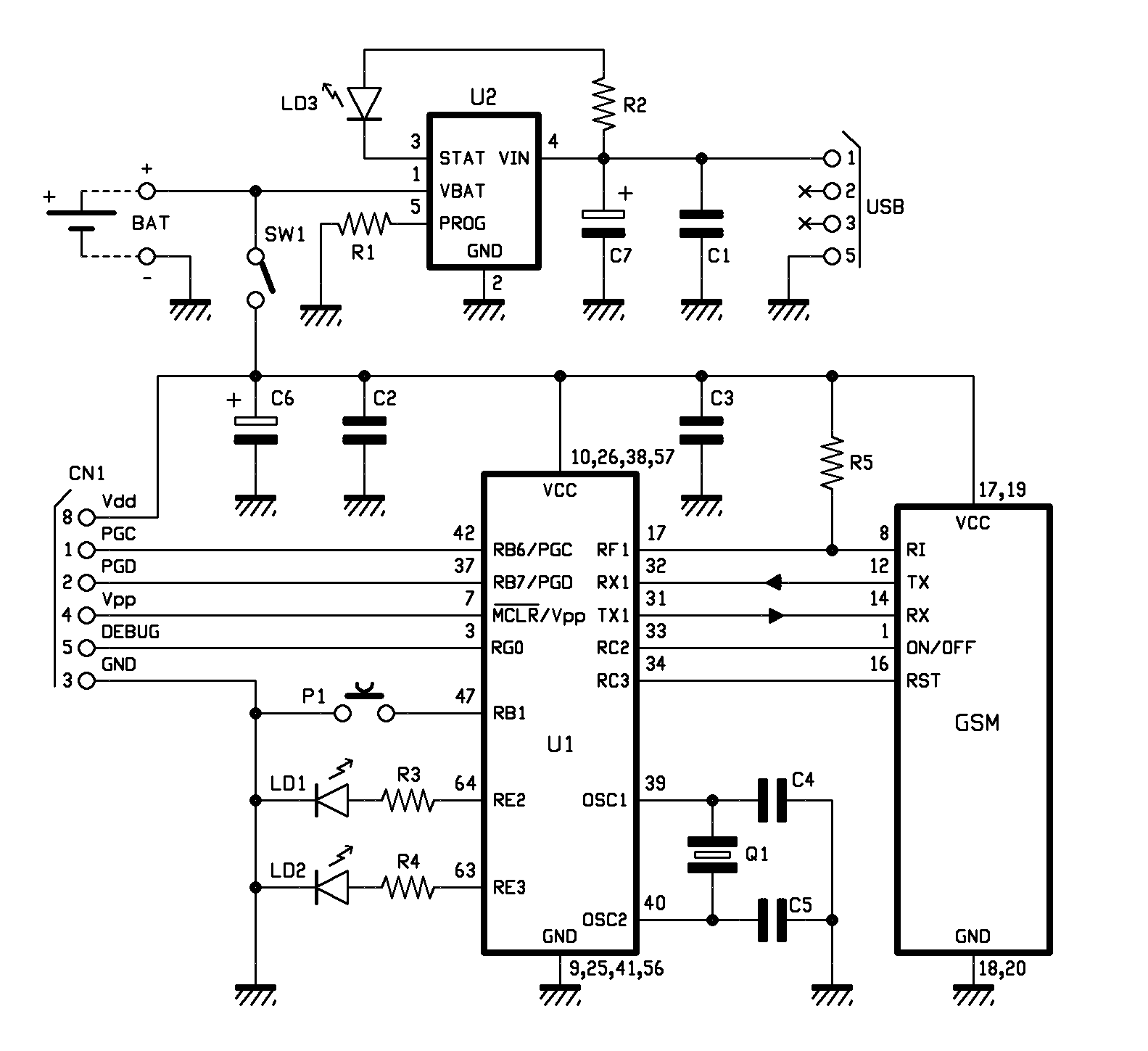
The circuit includes the mother board, mounting the microcontroller and its circuitry, and the daughter board mounting the communication module, the block named GSM in the schema. The reference numbers associated to the contacts on the GSM block correspond to the pins of the connector linking the daughterboard to the motherboard.
The program running in the microcontroller U1, one PIC18LF6722, waits for an incoming event or for the button P1 being pushed. While the button is pressed the line RB1, provided with internal pull-up resistor, switches from logical level 1 to the logical level 0, In case of incoming of an SMS message, the program reacts depending on the content of the message that could be a configuration message or a geographical position request.
Let focus on the process aimed to retrieve the geographical position, that is quite the same in both cases of manual request and P1 pushing (alarm or S. O. S. ). After the request has been detected, the program in the PIC microcontroller sends commands to the cellular module in order to have it connected to Internet in GPRS mode.
Then connects to the Google Maps server and sends a request of position based on the identification of the cell the SIMCom module is connected to; then again loop waiting for data on the RX channel of the UART. While got data back with the position (Latitude and Longitude) and accuracy, it is a composed string with the appropriate link to Google Maps and sent to the requesting phone, or to the phone number stored in memory coupled to the alarm function.
If the cellular phone is an Android Smartphone or an iPhone, the link received in the SMS can open Google Maps directly on the area where the localizer is present. In the other cases the message contains the coordinates and other data. The GSM module is managed by the microcontroller using the lines: RF1 (pin 8 on connector) through which it detects the incoming calls through the Ring Indicator (RI), RC7/RX1 (pin 14 on the cellular board); these last two are the lines, respectively, of reception and transmission of the UART used for receiving and sending SMS messages.
The same two lines are used for managing the SIM908, unless the reset and power supply lines. Power supply is controlled by line RC2 that affects pin 1 of the cellular module in order to turn ON and OFF the SIM908 and to enable the phone after initialization. Lines cited before are common to the GSM and GPS section of SIM908. To save power, there is the features to hibernate the localizer for a maximum period of 240 seconds.
This limits the power consumption of the micro and enables the possibility to put also the cellular in standby mode and reduce the system clock speed. In standby mode the cellular soaks only 6 mA of power. On SIM900 the Slow Clock can be enabled using the AT extended command AT+CSCLK=2. This command enables the Slow Clock mode automatically when there is no traffic on serial port and disabled it while new data comes in.
The microcontroller exits the hibernate mode when a new call come in or at the end of the period (240 seconds), in this case the microcontroller checks for possible SMS received. In the case, it executes and delivers the requests and, at the end, turn back in hibernate mode. While in hiber 🔗 External reference
Related Circuits
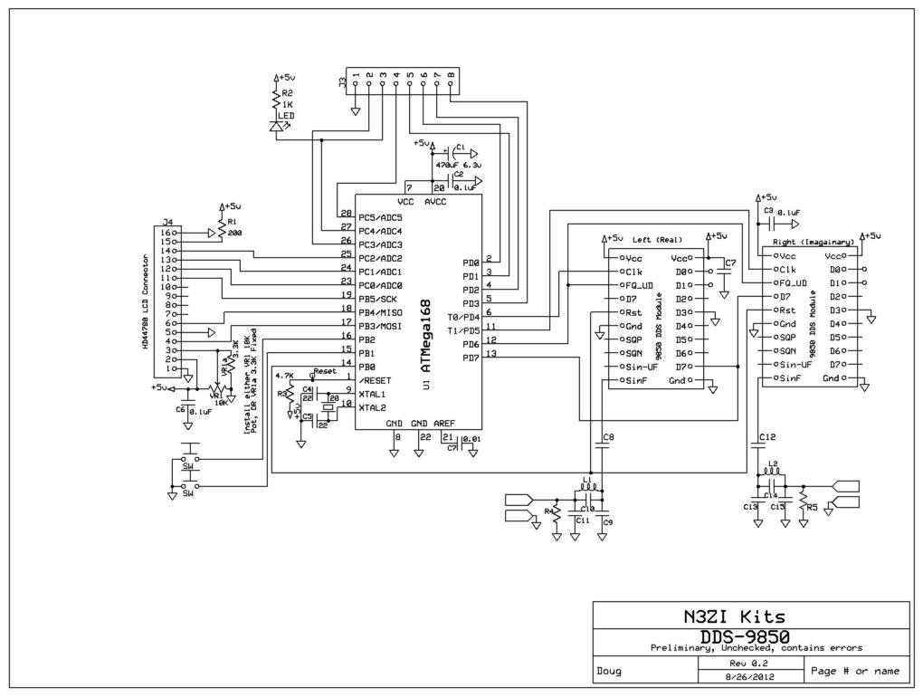
This project supports an LCD module (16x2 HD44780) and includes an AVR Micro ATMEGA168 programmed with demo/test code. It features a high-quality PCB made in the USA, which includes solder mask, plated through holes, and is RoHS compliant. The...
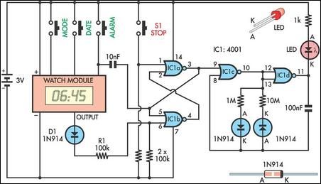
This device serves as a daily medication reminder. It incorporates a crystal watch and a 4001 quad 2-input NOR gate, with two of the gates (IC1a and IC1b) configured as an RS flip-flop. The watch is programmed to signal...
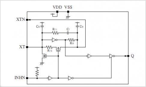
The CAMD CM8870 CM8870C offers complete DTMF receiver functionality by combining both the band-split filter and digital decoder capabilities into a single 18-pin DIP, SOIC, or 20-pin PLCC package. The CM8870C is produced using advanced CMOS process technology, ensuring...
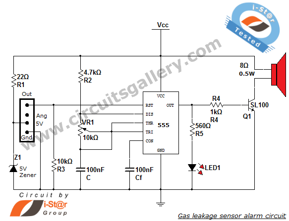
This article discusses a home security alarm circuit designed to detect LPG gas leakage. The circuit utilizes a gas sensor module, SEN 1327, which incorporates a QM 6 gas sensor. The output signal from this gas sensor module is...
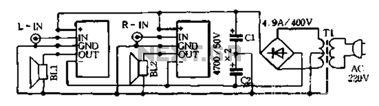
The D-200W module features a unique design that includes overload, overvoltage, overheating, short circuit, and reverse polarity protection, as well as shock protection for various speakers. The module employs a synchronous dynamic bias circuit to minimize static power consumption,...
Temperature sensor converter designed for use with a digital multimeter, capable of measuring temperatures from -40 °C to 110 °C. It features a state indicator and requires no calibration, utilizing the LM35 integrated circuit. The freezing point of water...