
guitar amplifier electronic 60 watt
The described guitar amplifier circuit is designed with a focus on simplicity and performance, making it suitable for various guitar amplification applications. The use of a single-rail power supply simplifies the design and reduces component count, which can lead to increased reliability and lower production costs. The capacitor coupling technique ensures that the DC component does not reach the speakers, protecting them from potential damage due to DC offsets.
The preamplifier section, utilizing a two-transistor gain block, is crucial for achieving the desired signal amplification while maintaining high input impedance. This feature is particularly important for preserving the integrity of the guitar signal, allowing for a more dynamic and responsive performance. The choice of transistors in this section directly influences the amplifier's gain characteristics and overall sound quality.
The output stage employs Darlington transistors, which are known for their high current gain. However, careful consideration must be given to the selection of these transistors to ensure they fit the design specifications without compromising the amplifier's size or thermal management. The inclusion of a sensing transistor (Q2) in close thermal contact with the output transistors is essential for effective thermal regulation, ensuring that the amplifier operates safely and efficiently under varying load conditions.
The harmonic modulation aspect of the amplifier is also significant, as it contributes to the tonal characteristics of the output signal. The choice of diodes for this purpose can greatly influence the harmonic content and overall sound. The recommendation to use 1N4148 diodes for a softer harmonic modulation reflects an understanding of the desired tonal qualities that guitarists often seek.
Finally, the adjustment of resistor R9 for voltage measurement is a critical step in the calibration process. This adjustment ensures that the output waveform remains symmetrical, which is vital for achieving optimal sound quality and preventing distortion at high output levels. Utilizing an oscilloscope for this adjustment allows for precise tuning, enhancing the amplifier's performance in real-world applications. Overall, this amplifier design combines simplicity with effective sound shaping capabilities, making it a valuable tool for guitarists.This Guitar Amplifier electronic architecture adopts a able-bodied accustomed ambit cartography for the ability amplifier, application a single-rail accumulation of about 60V and capacitor-coupling for the speaker(s). The advantages for a guitar amplifier are the actual simple circuitry, alike for analogously aerial ability outputs, and a assertiv
e congenital amount of loudspeaker protection, due to capacitor C8, preventing the voltage accumulation to be conveyed into loudspeakers in case of achievement transistors` failure. The preamp is powered by the aforementioned 60V balustrade as the ability amplifier, acceptance to apparatus a two-transistors gain-block able of carrying about 20V RMS output.
This provides a actual aerial ascribe afflict capability. * The Darlington transistor types listed could be too oversized for such a design. You can substitute them with MJ11014 (Q3) and MJ11013 (Q4) or TIP142 (Q3) and TIP147 (Q4). * D1 and D2 can be any Schottky-barrier diode types. With these devices, the harmonic modifier operation will be hard. Using for D1 and D2 two common 1N4148 silicon diodes, the harmonic modifier operation will be softer. * In all cases where Darlington transistors are used as the output devices it is essential that the sensing transistor (Q2) should be in as close thermal contact with the output transistors as possible.
Therefore a TO126-case transistor type was chosen for easy bolting on the heatsink, very close to the output pair. * R9 must be trimmed in order to measure about half the voltage supply from the positive lead of C7 and ground.
A better setting can be done using an oscilloscope, in order to obtain a symmetrical clipping of the output waveform at maximum output power. 🔗 External reference
Related Circuits
Cats are natural predators of rats, and the use of electronic devices to simulate meowing sounds as a repellent is an effective method. These electronic devices can produce meowing sounds at various frequencies and intervals, making them suitable for...

This lie detector circuit provides two readings: one for difficult questions and another for the subject's general emotional state. Two flexible, uninsulated wires wrapped around the fingers or wrist can serve as electrodes. Each change in resistance, and consequently...
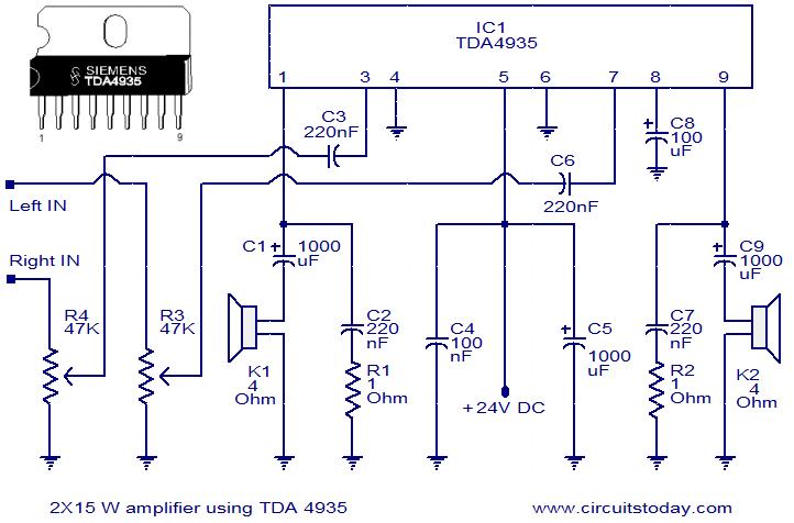
The TDA4935 is a bipolar stereo amplifier integrated circuit (IC) that can be configured as either a 2x15W stereo amplifier or a 30W mono BTL (Bridge-Tied Load) amplifier. This IC includes built-in circuitry for overload protection and over-temperature shutdown....
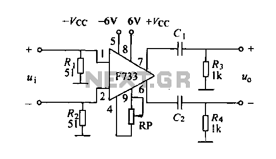
The F733 integrated wideband amplifier is a common-emitter configuration that features a total wideband amplifier with an internal feedback circuit. It is compact, offers zoom capability, and exhibits excellent circuit stability. The F733 circuit, as illustrated in the accompanying...
The circuit is simple, yet is capable of excellent performance. I designed it specifically for use as an amplifier for the digital sound card in my computer. Audio input can be from any two-channel line level device such as...
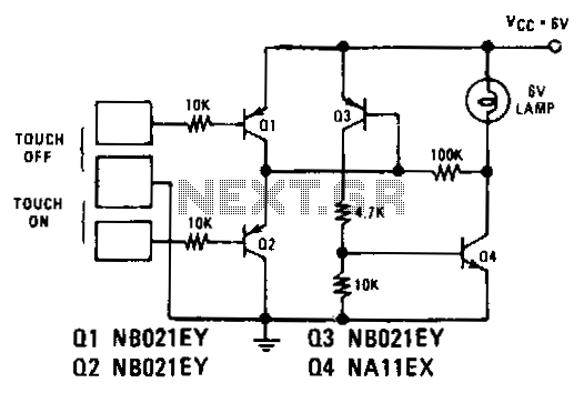
Transistors Q1 and Q2 control latches Q3 and Q4 to switch on the lamp. A high resistance from touching the electrode biases Q1 or Q2 on, setting or resetting the latch. In this circuit, transistors Q1 and Q2 function as...