
Simple lie detector circuit design electronic project

The lie detector circuit operates by measuring the skin's electrical resistance, which can change in response to emotional stimuli. This resistance is influenced by the sweat glands' activity, which is often heightened during stress or anxiety. The circuit utilizes two electrodes positioned on the subject's fingers or wrist to capture these changes in resistance.
Operational amplifier A1 serves as the primary amplifier, boosting the small voltage changes resulting from resistance variations. The output from A1 is processed through resistor R3, which helps in translating this amplified signal into a readable deviation on the measuring device, providing insight into the subject's physiological responses during questioning.
Operational amplifier A2 is configured as an integrator, which plays a crucial role in stabilizing the measurements by averaging out transient fluctuations in skin resistance. This integration process is essential to ensure that the readings are reflective of the subject's emotional state over a defined period rather than capturing momentary spikes.
The timing aspect of the circuit, governed by components R5, C2, and C3, establishes a measurement window during which the skin resistance is evaluated. The inclusion of diodes D1 and D3 enhances the circuit's responsiveness, allowing for immediate feedback to the measuring device, which is critical in a lie detection scenario where timing can be crucial.
Potentiometer P1 provides an adjustable time delay feature, allowing the operator to fine-tune the circuit to accommodate different subjects or scenarios. Adjustments to resistance R1, which can be substituted with a potentiometer, enable calibration of the circuit based on individual differences in skin resistance. This adaptability is vital for achieving accurate readings across a diverse range of users.
In summary, this lie detector circuit leverages the principles of electrical resistance and operational amplification to provide a nuanced understanding of an individual's emotional state, making it a valuable tool in psychological assessments and interrogation settings.This lie detector circuit described eally give two readings: one for the difficult questions and one show subject general emotional state. As electrodes can be used two flexible wires, uninsulated wrapped around the fingers or wrist. Each change of resistance, and therefore the voltage at the input circuit will be amplified by operational amplifie
r A1, which is also an upstairs separately corresponding output signal will, by R3, a deviation of the measuring device. Operational amplifier A2 is connected as an integrator and allows the circuit to automatically adjust according to the average resistance of the skin.
The length of time in skin resistance to be measured is determined by R5, C2 and C3. Until this time elapses, the gauge does not give any indication, though diodes D1 and D3 ensure a rapid response of the circuit. P1 potentiometer allows adjustment of time delay circuit. Because skin resistance varies from person to person, it may be necessary to change the resistance value R1.
This resistance can be replaced by a potentiometer. Read a great value to the instrument connected to port B indicates that the subject`s skin resistance is low. 🔗 External reference
Related Circuits
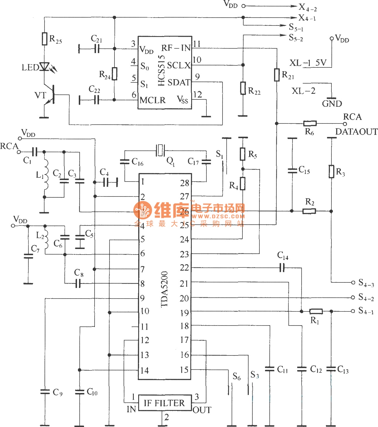
The TDA5200 is a low-power, single-chip ASK superheterodyne receiver circuit. It operates within two frequency blocks: 868 to 870 MHz and 433 to 435 MHz. This circuit is highly integrated, requiring minimal external components while offering excellent functionality. It...
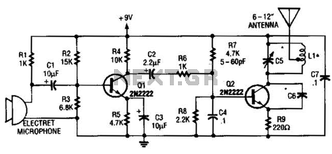
The vacuum tube remains relevant and functional in certain applications, such as in this continuous wave (CW) transmitter. The circuit is constructed in a traditional breadboard style on a wooden base. Old table radios serve as a valuable source...
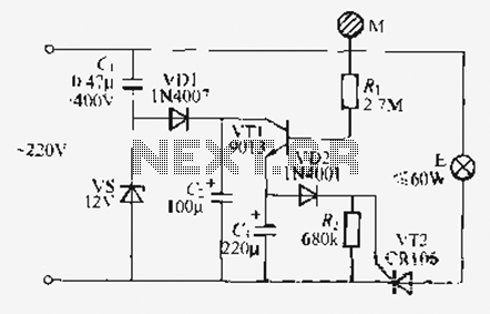
Utilize the call sheet to touch the electrical threshold M, which causes the E lamp to light up. When the same interval subparagraph is triggered, the lights will automatically turn off. A voltage regulator rectifier circuit is formed using...
NOTE: There is no guarantee as to the suitability of said circuits and information for any purpose whatsoever other than as a self-training aid. I.E. If it blows your equipments, trashes your hard disc, wipes your backup, burns your...
The TEA5764UK is a single-chip, electronically tuned FM stereo radio that includes a Radio Data System (RDS) and Radio Broadcast Data System (RBDS) demodulator, along with an RDS/RBDS decoder. This device is designed for portable applications and features fully...
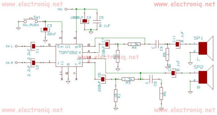
TDA7262 stereo 20 watts audio amplifier circuit design electronic project The TDA7262 is an integrated circuit designed for stereo audio amplification, capable of delivering up to 20 watts per channel. This amplifier circuit is suitable for various applications, including home...
Warning: include(partials/cookie-banner.php): Failed to open stream: Permission denied in /var/www/html/nextgr/view-circuit.php on line 713
Warning: include(): Failed opening 'partials/cookie-banner.php' for inclusion (include_path='.:/usr/share/php') in /var/www/html/nextgr/view-circuit.php on line 713