
Guitar Effect Circuit : Electro Harmonix Big Muff Pi

The Electro Harmonix Big Muff Pi is a renowned distortion and fuzz pedal commonly used in electric guitar applications. The circuit typically consists of multiple stages of gain and clipping, allowing for a wide range of tonal possibilities.
To enhance the performance and usability of the Big Muff Pi, a contemporary input-jack power connection can be integrated. This modification would provide a more reliable power source and potentially improve the overall noise performance of the circuit. The use of a DPDT (Double Pole Double Throw) bypass switch is also advisable. This switch allows for true bypass operation, ensuring that when the effect is disengaged, the signal path remains unaltered, preserving the original tone of the instrument.
While the specific transistors and diodes used in the circuit remain unspecified, it is essential to select high-quality components to maintain the desired sound characteristics. Transistors typically used in fuzz circuits include silicon and germanium types, each contributing distinct tonal qualities. Diodes, often used for clipping, can also significantly affect the sound, with options ranging from standard silicon diodes to more exotic choices like LED or germanium diodes.
In conclusion, implementing a modern input-jack power solution and a DPDT bypass switch, along with carefully selected high-quality transistors and diodes, can enhance the functionality and sound quality of the Electro Harmonix Big Muff Pi circuit, making it more suitable for contemporary use.This Electro Harmonix Big Muff Pi circuit would most likely be better making the change by a contemporary input-jack power and a DPDT bypass switch. The kinds of transistors and diodes are unknown. It really is most likely that any high acq.. 🔗 External reference
Related Circuits
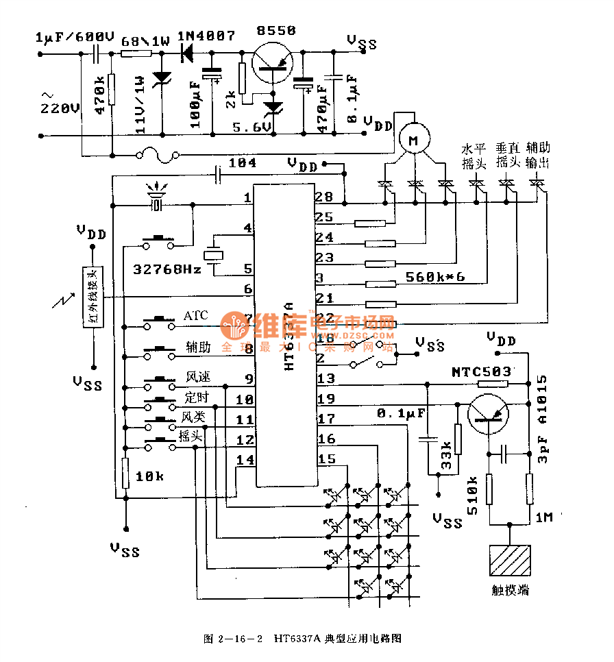
The HT6337 is an infrared remote control receiving decoder circuit specifically designed for electric fan applications. It is housed in a 28-pin dual-row DIP package, with the compatible model being HT12C. The HT6337 is part of a series of...
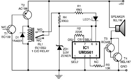
This heat detector alarm electronic project is designed using the UM3561 sound generator circuit and several common electronic components. The heat detector circuit employs a complementary pair of npn and pnp transistors to sense heat. When the temperature near...

This is a variation of Mr. Marian's "Simple Micro Ampere Meter Circuit" that employs active circuitry and an analog meter to measure sensitive DC currents. The circuit in question is designed to provide precise measurements of very low DC currents,...
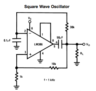
Here is a small LM386-based square-wave oscillator constructed from the following schematic. A 50k potentiometer was used in place of a 30k resistor, which functions as a pitch controller. The audio provided consists of track recordings made in Ableton...

This voltage regulator and current limiter combination can be constructed using two 7805 regulators as illustrated. Resistors R1, R2, and R3 should be chosen to achieve a 5-V drop at the maximum allowable current limit. Switch S1 selects one...
This is a straightforward and effective LED circuit that can be powered directly from an AC mains supply ranging from 100 volts to 230 volts. The circuit can serve as a mains power indicator or a night lamp. Resistors...