
Mains Operated LED Circuit
The described LED circuit operates on the principle of using a series combination of resistors and a capacitor to limit the current flowing through the LED. The circuit is connected directly to the AC mains, which allows it to illuminate the LED without the need for a transformer or additional power supply components.
In this configuration, R1 and R2 are chosen based on the desired brightness of the LED and the maximum current rating of the LED. Typically, these resistors are valued to allow a safe current to flow through the LED, which is usually rated for around 20 mA for standard applications. The capacitor C1 serves a dual purpose: it not only helps in current limiting but also provides a phase shift that allows the LED to operate effectively with the alternating current.
The immunity to voltage spikes and surges is achieved through the proper selection of components and their ratings. The resistors must be able to withstand the maximum voltage that may appear across them, while the capacitor should have a voltage rating significantly higher than the maximum expected AC voltage to avoid breakdown.
This LED circuit can be utilized in various applications, including as a power indicator for appliances, a night lamp for low-light environments, or as a simple visual alert for various electronic devices. Its simplicity and effectiveness make it a popular choice for both hobbyists and professionals in the field of electronics.Here is a simple and powerful LED circuit that can be operated directly from the AC 100 volt to AC 230 Volts mains supply. The circuit can be used as mains power locator or night lamp etc.. The resistor R1,R2 and capacitor C1 provides necessary current limiting. The circuit is sufficiently immune against voltage spikes and surges.. 🔗 External reference
Related Circuits
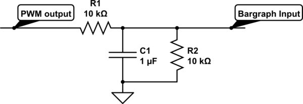
For a project, there is a need to display a progress bar representing the activity performed by a microcontroller unit (MCU). A bar graph display is intended for this purpose; however, the bar graph display driver IC, LM3914, requires...
This circuit functions to monitor the duration of occupancy in a toilet, activating an alert if the time spent exceeds a predefined limit. The components involved include a resistor, integrated circuit (IC), capacitor, and transistor. The occupancy monitoring circuit is...

The schematic diagram below illustrates a basic sample-and-hold circuit utilizing the CA3140 as the readout amplifier for the memory capacitor. The CA3080A is also employed in the design. The sample-and-hold circuit is a crucial component in analog-to-digital conversion systems, allowing...

This direct-conversion receiver utilizes a TDA7000 integrated circuit (IC) and incorporates an LM386 audio amplifier. The TDA7000 serves as the mixer and local oscillator (L.O.) section. The frequency control can be achieved using either an air variable capacitor or...
This is a digital calendar circuit that utilizes a microcontroller to display the date, day, and month on an LED display. The entire system is managed by an 8-bit microcontroller, which operates based on a program embedded in its...
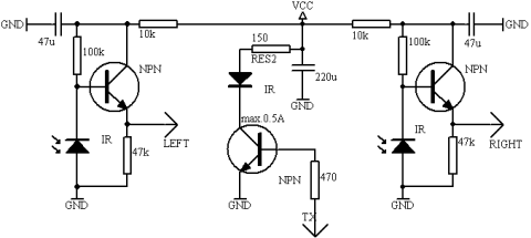
Long-distance infrared transmitter circuit diagram. This simple circuit offers a considerable range by utilizing three infrared transmitting LEDs (IR1 through IR3) in series to enhance the radiated power. To further improve directivity and power density, the IR LEDs can...
Warning: include(partials/cookie-banner.php): Failed to open stream: Permission denied in /var/www/html/nextgr/view-circuit.php on line 713
Warning: include(): Failed opening 'partials/cookie-banner.php' for inclusion (include_path='.:/usr/share/php') in /var/www/html/nextgr/view-circuit.php on line 713