
AC/DC Microammeter Circuit
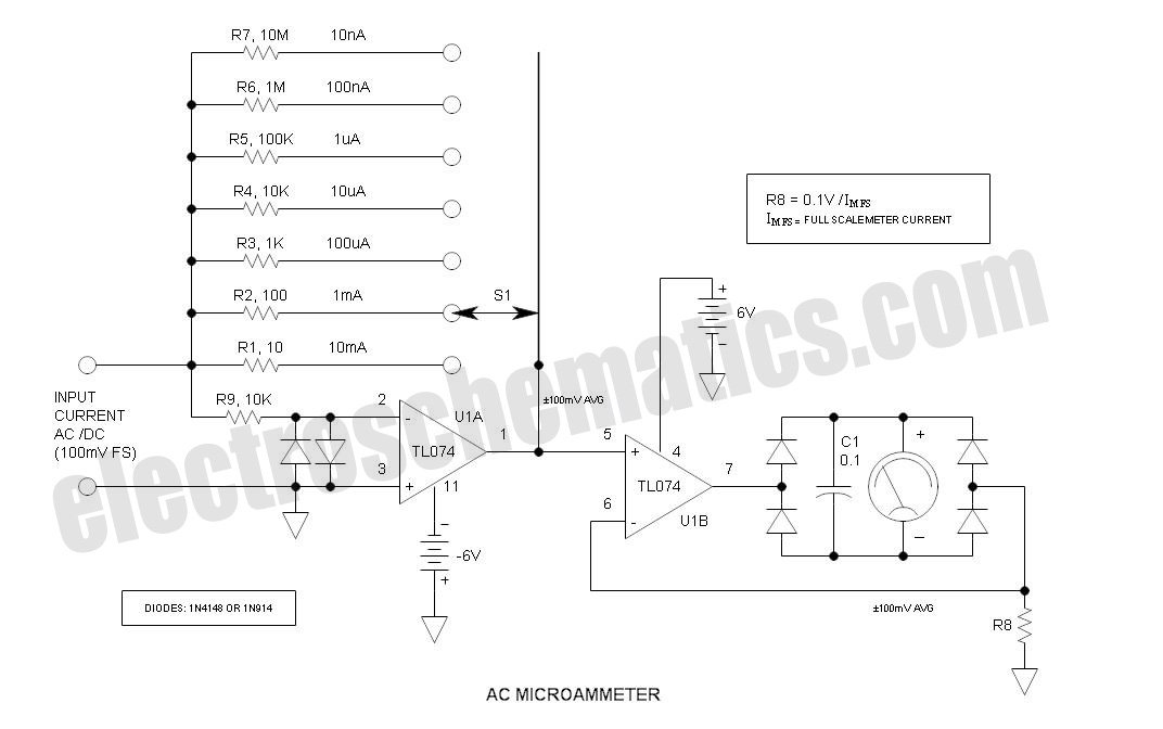
The circuit in question is designed to provide precise measurements of very low DC currents, often in the microampere range. It typically incorporates an operational amplifier (op-amp) to amplify the small signals received from the current sensing element. The circuit may include a shunt resistor placed in series with the load to develop a measurable voltage drop proportional to the current flowing through it.
The output from the op-amp is fed to an analog meter, which is calibrated to display the current reading accurately. The choice of an analog meter allows for a visual representation of the current flow, making it easier to observe fluctuations in real-time.
The design may also feature additional components such as resistors for gain setting, capacitors for filtering noise, and possibly diodes for protection against reverse polarity. The power supply for the circuit should be stable and capable of providing the necessary voltage levels to ensure accurate readings.
Overall, this micro ampere meter circuit is suitable for applications in laboratories, electronics testing, and other scenarios where precise low-current measurements are required. Proper calibration and component selection are crucial to achieving optimal performance and accuracy in the readings.This is a take-off on Mr. Marian s ""Simple Micro Ampere Meter Circuit"" that utilizes active circuitry and an analog meter to make sensitive DC current meas.. 🔗 External reference
Related Circuits
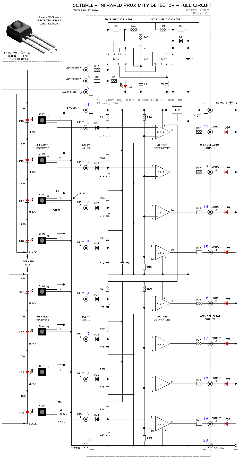
The circuits on this page are for an Infrared Proximity Detector using the Vishay Electronics TSOP4830, which is an IR Receiver Module designed for remote control systems. The TSOP4830 functions as a sensitive infrared detector that operates without requiring...
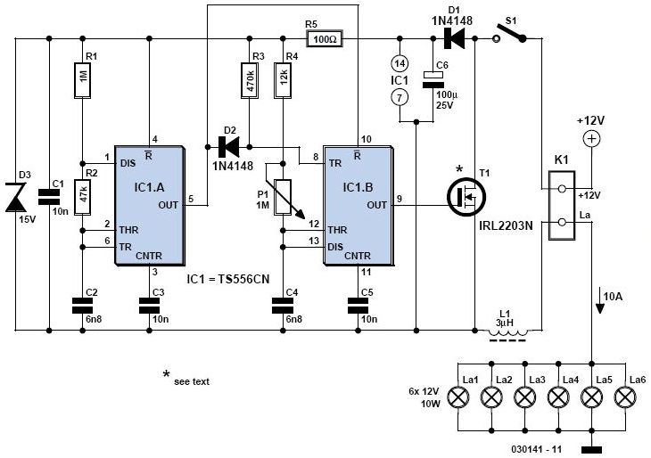
A light dimmer is quite uncommon in a caravan or on a boat. This document outlines how to create one, allowing for mood adjustment when needed. A light dimmer circuit is an essential component for enhancing the ambiance in confined...
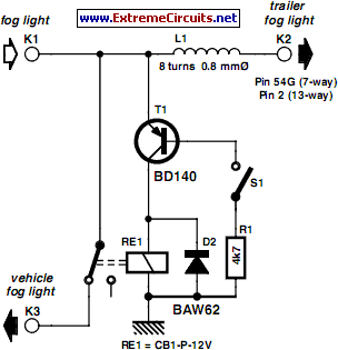
In many countries, it is now mandatory or at least recommended to have a rear fog light on a trailer. There is an additional requirement that when the trailer is connected to the vehicle, the rear fog light of...
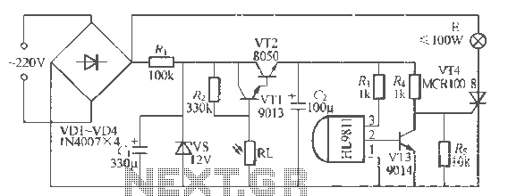
The H1.9811 single-channel flash control integrated circuit from Wuxi Love Core Microelectronics Co., Ltd. is designed for controlling flashing warning lights in road barricades. It features an integrated internal RC oscillator, frequency divider, output buffer amplifier, shaping circuit, and...
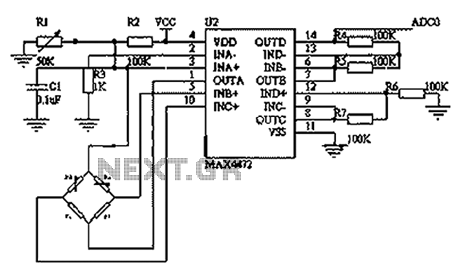
This circuit utilizes a BP01-type pressure sensor and the MAX4472 operational amplifier. The BP01 pressure sensor is specifically designed for blood pressure detection and is primarily used in portable electronic sphygmomanometers. It features a precision thick film ceramic chip...
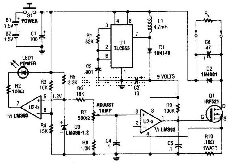
Useful for low-resistance measurements, this 1-A current source will produce 1 A in unknown resistance Rx. For best results, Rc should be less than 1 to 2, because only 3 V are available. Ul is a flyback converter to...