
Guitar phaser effect
This phaser circuit utilizes 11 operational amplifier sections, typically using the LM324, which can be substituted with other compatible op-amps. The circuit operates on a dual rail power supply of ±9V, with a designated ground (0V) indicated by a chassis symbol. It is essential to ensure that the power supplies are properly decoupled to prevent noise and instability in the circuit operation. A spare section of the IC can be employed to create a center tap from an 18V supply if needed.
At the heart of the circuit is an LED that illuminates six cadmium sulfide (CdS) photoresistors, or light-dependent resistors (LDRs). These LDRs are strategically arranged in a circular formation around the LED to ensure uniform illumination. While precise matching of the LDRs is not critical, the assembly must be shielded from ambient light to avoid interference with the phasing effect.
Each CdS cell functions as a variable resistor within a single variable phase-shift circuit. The configuration includes six individual phase shifters connected in series, with each stage contributing to the overall phase shift of the signal. The brightness of the LED is modulated by an oscillator located in the lower section of the circuit. The frequency of this oscillator can be adjusted using a Speed potentiometer, allowing for control over the modulation rate. The design ensures that the LED remains illuminated, providing a range of maximum and minimum brightness settings.
The LDRs play a crucial role in controlling the phase shift across the six stages of the phase shifter. The circuit incorporates feedback to enhance the phasing effect, with the Intensity control allowing for adjustments to the overall phase shift intensity.
Additionally, an input buffer is included in the upper right section of the circuit. This buffer serves to isolate the input signal, providing a clean feed to the phase shifter while also routing the processed signal to a mixer stage. In this mixer stage, the phased signal is combined with the original input signal, allowing for a rich and textured audio output.
This discrete phaser circuit effectively demonstrates the underlying principles of phase shifting and modulation, contrasting with modern phaser designs that typically employ digital delay lines. The construction and operation of this circuit provide valuable insight into analog signal processing techniques used in audio effects.This circuit is a phaser circuit, as used in guitar foot-pedal effects. It used 11 sections of op-amp such as LM324 but others will do. The whole circuit works of a dual rail supply: +/- 9v. The 0v rail is indicated by a chassis sign. Make sure these supplies are well decoupled. There is a spare section of one of the IC's which you could used to derive a center tap from an 18v supply. The circuit works by means of an LED illuminating six cadmium sulphide photo sensitive resistors or LDRs: these six should be arranged in a circle around the LED so that they all get illuminated approximately the same.
Exact matching does not matter too much. The whole photo assembly should, of course, be shielded from external lighting. Each CdS cell acts as a variable resistor in a single variable phase-shift circuit and there are six such individual phase shifters arranged in series, each increasing the overall shift. The LED's brightness is modulated by an oscillator (bottom section of the circuit) whose frequency can be adjusted by the Speed pot.
Max and min illumination are adjustable - the LED should not extinguish. The LDRs control the shift of the six stages of the phase shifter. This phase shifter has overall feedback, varied by the Intensity control, to alter the intensity of the phasing effect by altering the overall phase shift. Apart from that, there is an input buffer (top right) whose output feeds the phase shifter and also feeds through to the mixer stage where it is mixed with the phased signal.
I hope there are no errors in the circuit but it is given as is, without any obligation but of course we will answer all reasonable queries. Unfortunately I have been out of audio for some time now so cannot give too much assistance. Modern phasers will use a digital delay line circuit, but this discrete version works and illustrates all the principles involved.
🔗 External reference
Related Circuits
This tremolo effect circuit utilizes the XR2206 and the TCA730 integrated circuits, which are designed as an electronic balance and volume regulator with frequency correction. The tremolo effect circuit operates by modulating the amplitude of an audio signal, creating a...
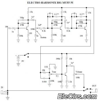
The Electro Harmonix Big Muff Pi circuit would likely benefit from the incorporation of a modern input-jack power connection and a DPDT bypass switch. The specific types of transistors and diodes used in the circuit are not specified. It...
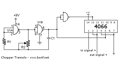
A tremolo is an effect unit that modulates the amplitude of the guitar signal, typically using a triangular waveform. This particular version employs a square waveform, resulting in a more abrupt, chopping effect. Such effects are prominently featured in...

A cost-effective nickel-cadmium battery charger using the LM393, featuring the following characteristics: (1) It provides constant current charging interspersed with high current discharge. The charging current is approximately 300mA, while the discharge current increases with battery voltage, reaching nearly...
There are at least three different versions of this circuit. The first DM-2 version utilized the MN3005 BBD and the MN3101 Clock Driver IC (PCB marking: ET5214-510). Later, the clock driver was changed to the MN3102, and the BBD...
This type of circuit cannot be employed in a load-sharing configuration. Synchronous rectification is one of the most effective methods to enhance the efficiency of low-voltage systems. Synchronous rectification is a technique employed in power conversion circuits, particularly in DC-DC...
Warning: include(partials/cookie-banner.php): Failed to open stream: Permission denied in /var/www/html/nextgr/view-circuit.php on line 713
Warning: include(): Failed opening 'partials/cookie-banner.php' for inclusion (include_path='.:/usr/share/php') in /var/www/html/nextgr/view-circuit.php on line 713