
The Effects of Turning off a Converter with Self-Driven Synchronous Rectifiers
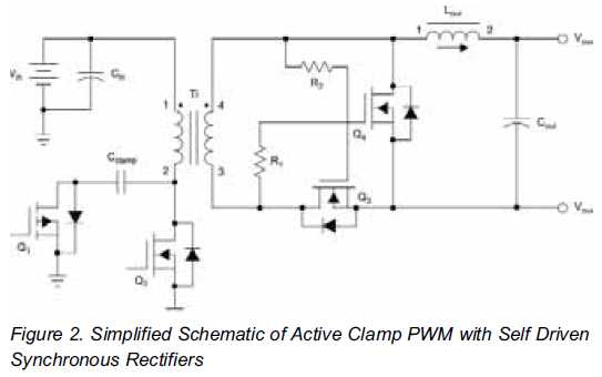
Synchronous rectification is a technique employed in power conversion circuits, particularly in DC-DC converters and power supplies, to improve efficiency by reducing conduction losses. Unlike traditional diode rectification, where diodes are used to convert AC to DC, synchronous rectification utilizes active switching devices, typically MOSFETs, to perform the rectification process. This approach significantly minimizes the forward voltage drop associated with diodes, leading to lower power dissipation and improved thermal performance.
In a synchronous rectifier circuit, the control mechanism is crucial for determining the optimal timing for switching the MOSFETs. This is often achieved through feedback loops that monitor the output voltage and adjust the gate signals of the MOSFETs accordingly. The synchronous rectifier operates in conjunction with a PWM (Pulse Width Modulation) controller, which regulates the duty cycle of the switching devices to maintain the desired output voltage level.
The implementation of synchronous rectification is particularly beneficial in low-voltage applications, where the efficiency gains can result in significant power savings and reduced heat generation. However, it is important to note that synchronous rectification circuits typically require more complex control strategies and may not be suitable for all applications, particularly those requiring load-sharing configurations. In such scenarios, careful design considerations must be made to ensure stability and reliability in the power delivery system.This type of circuit can never be used in a load-share configuration Synchronous rectification is one of the best ways to improve the efficiency of the low-voltage.. 🔗 External reference
Related Circuits

The circuit serves as a signal source for calibration level meters or sensor-driven differential transformers. The oscillation frequency is determined by the 74HC04, producing a frequency of 1 kHz through resistor R. The supply voltage of the circuit changes...
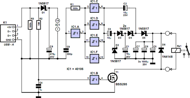
How often does it happen that a user shuts down Windows and then forgets to turn off the computer? This circuit automates that process. After Windows is shut down, a click occurs a second later, disconnecting the PC from...
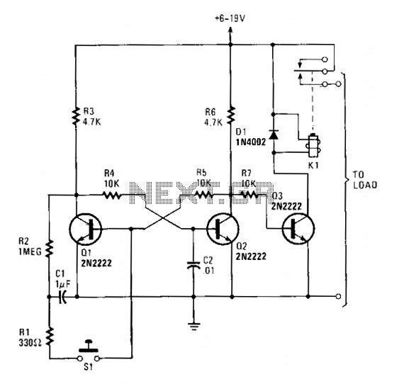
Transistors Q1 and Q2 form a flip-flop configuration, while Q3 operates a reed relay. Upon initial power application to the circuit, Q1 and Q3 are in a conducting state, whereas Q2 remains off. A momentary closure of switch S1...
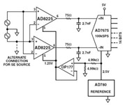
The Common Mode Rejection Ratio (CMRR) facilitates the rejection of high-frequency common-mode voltages, leading to the attenuation of elevated ambient noise levels from utility lines, industrial machinery, and other sources of radiation. The circuit diagram presented illustrates the advantages...
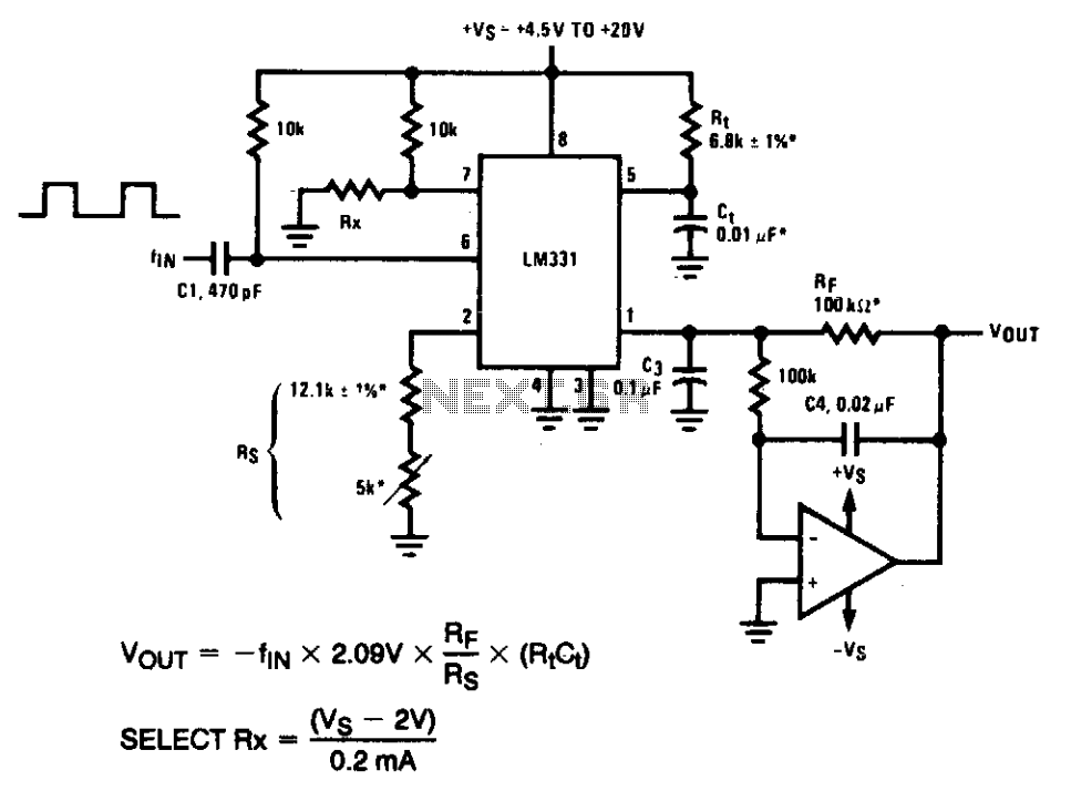
In the precision circuit, an operational amplifier provides a buffered output and also functions as a 2-pole filter. The ripple will be less than 5 mV peak for all frequencies above 1 kHz, and the response time will be...
The ADF4107 Frequency Synthesizer can be used to implement local oscillators in the upconversion and downconversion sections of wireless receivers and transmitters. It consists of a low noise digital phase frequency detector (PFD), a precision charge pump, a programmable...