
Guitar Reverb

The reverb driver amp consists of a phase inverting push-pull circuit made from dual sections of a 5532 high quality audio op-amp. This provides a voltage swing of approximate twice the supply voltage to the reverb impedance matching transformer, allowing higher power transfer. The transformer matches the impedance of the driver amplifier to the reverb driver coil and allows a dual phase driving signal to power a reverb coil with one grounded side. The transformer is a standard "70 volt" audio line transformer that is o
The second-generation guitar reverb circuit is designed to enhance audio fidelity significantly compared to its predecessor, making it an effective front-end solution for guitar amplifiers. The circuit architecture includes a class A input stage, which utilizes a 2N3906 PNP transistor to ensure low noise operation. This transistor is configured with an adjustable bias to optimize performance based on varying input conditions.
The output from the preamp stage is strategically routed to three destinations: the output mixer amplifier, the reverb driver amplifier, and the input clipping detector. This multi-path design allows for versatile signal processing and monitoring of gain levels. The inclusion of clipping indicators at both the preamp and reverb recovery stages aids in achieving optimal gain settings, preventing distortion and ensuring signal integrity.
The reverb driver amplifier is constructed using a phase-inverting push-pull configuration, which leverages dual sections of a 5532 op-amp. This configuration is crucial as it allows for a voltage swing that can reach approximately twice the supply voltage, thereby enhancing the power transfer to the reverb impedance matching transformer. This transformer plays a vital role in ensuring that the output from the driver amplifier is efficiently matched to the reverb driver coil.
The use of a standard "70 volt" audio line transformer facilitates the generation of a dual phase driving signal, which is essential for powering the reverb coil while maintaining one grounded side. This setup not only optimizes the transfer of power but also contributes to the overall fidelity and performance of the reverb effect, making it suitable for professional audio applications. The design considerations in this circuit ensure that it meets the demands of modern guitar amplification systems, providing musicians with enhanced sound quality and versatile functionality.This is my second-generation guitar reverb circuit. The fidelity is much improved over the earlier design, it is suitable for use as a front-end to a guitar amplifier. This circuit features clipping indicators on the preamp and reverb recovery stages, allowing for the optimal gain settings.
The guitar input stage is a class A amplifier with adjustable bias. A 2N3906 PNP tranistor is used for a low noise design on this stage. The output of the preamp stage is sent to three places: the output mixer amp, the reverb driver amp, and the input clipping detector. The reverb driver amp consists of a phase inverting push-pull circuit made from dual sections of a 5532 high quality audio op-amp.
This provides a voltage swing of approximate twice the supply voltage to the reverb impedance matching transformer, allowing higher power transfer. The transformer matches the impedance of the driver amplifer to the reverb driver coil and allows a dual phase driving signal to power a reverb coil with one grounded side. The transformer is a standard "70 volt" audio line transformer that is o 🔗 External reference
Related Circuits
In all instances where Darlington transistors serve as output devices, it is crucial for the sensing transistor (Q4) to maintain close thermal contact with the output transistors. Consequently, a TO126-case transistor type was selected for ease of mounting onto...
The AB763 Super Reverb is a highly regarded Fender amplifier known for its rich tone, durability, and the classic sound derived from the traditional blackface AB763 design. This design was also utilized in some silverface amplifiers produced between 1967...
This schematic represents a simple JFET buffer derived from the Basic Buffers article in the AMZ Lab Notebook, enhanced with pulldown resistors at both the input and output. The circuit features high input impedance and low output impedance, making...
Build a Guitar Looper with an Arduino board. Here is how to produce a pedalboard for electric guitar. The idea is to connect pedals to the Arduino and to use them to control a software of sound processing in...
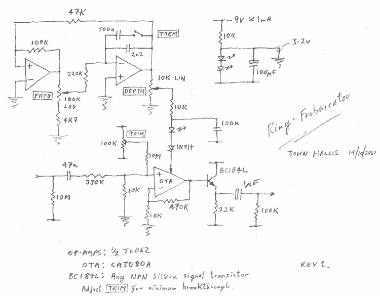
This is a ring-modulator which doubles as a tremolo. It was designed as a replacement for the somewhat over-complicated ElectroHarmonix Frequency Analyzer with its ridiculous high-voltage wall-wort and huge metal box. I've got it down to a 3080 OTA...

This design utilizes a well-established circuit topology for the power amplifier, employing a single-rail supply of approximately 60V and capacitor coupling for the speaker(s). The benefits for a guitar amplifier include simple circuitry, even with relatively high power outputs,...