
Guitar Reverb Effect
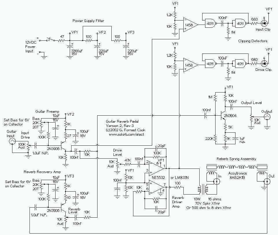
The circuit comprises several key components that function together to create a high-fidelity audio signal processing chain suitable for electric guitar applications. The input stage, utilizing a class A amplifier configuration, ensures that the guitar signal is amplified with minimal distortion. The choice of the 2N3906 PNP transistor is essential for achieving low noise performance, which is critical in preserving the integrity of the guitar's tonal characteristics.
The output of the preamp stage is strategically routed to three distinct destinations: the output mixer amplifier, the reverb driver amplifier, and the input clipping detector. This multi-path configuration allows for versatile signal processing, enabling simultaneous effects and monitoring.
The reverb driver amplifier employs a phase inverting push-pull topology using dual sections of the 5532 op-amp. This setup is designed to provide a substantial voltage swing, approximately double the supply voltage, which is crucial for driving the reverb impedance matching transformer effectively. The transformer plays a vital role in interfacing the driver amplifier with the reverb driver coil, ensuring optimal power transfer and minimizing signal loss.
A 100-ohm resistor is integrated into the circuit to stabilize the output signal. This component is critical for preventing saturation of the op-amps when driving the transformer, which could introduce distortion into the audio signal. The careful selection of this resistor value is essential for maintaining the fidelity of the output signal.
The transformer itself is a standard "70 volt" audio line transformer, which is specifically designed to match the impedance of the driver amplifier to the reverb driver coil. This impedance matching is necessary to facilitate a dual-phase driving signal, allowing for effective operation of the reverb coil while maintaining one side grounded, thereby reducing potential noise and interference in the audio path.
Overall, this circuit design exemplifies a thoughtful approach to audio signal processing, combining high-quality components and configurations to achieve a desirable sound output for electric guitar applications.The guitar input stage is a class A amplifier with adjustable bias. A 2N3906 PNP tranistor is used for a low noise design on this stage. The output of the preamp stage is sent to three places: the output mixer amp, the reverb driver amp, and the input clipping detector. The reverb driver amp consists of a phase inverting push-pull circuit made from dual sections of a 5532 high quality audio op-amp.
This provides a voltage swing of approximate twice the supply voltage to the reverb impedance matching transformer, allowing higher power transfer. The 100 ohm resistor is critical for insuring a clean drive signal, without it, the op-amps can saturate when driving the transformer, producing unwanted distortion.
The transformer matches the impedance of the driver amplifer to the reverb driver coil and allows a dual phase driving signal to power a reverb coil with one grounded side. The transformer is a standard "70 volt" audio line transformer that is o 🔗 External reference
Related Circuits
This circuit uses the Holtek HT2884 IC to produce 8 different sound effects. All sound effects are generated internally by the HT2884 IC. Power is a 3 Volt battery, but the IC will work with any voltage between 2.5...
This text provides information about an initial attempt at creating a circuit, referencing a schematic found in an application note for a specific module. However, it notes that the schematic did not include details for the power supply circuitry,...

A cost-effective nickel-cadmium battery charger using the LM393, featuring the following characteristics: (1) It provides constant current charging interspersed with high current discharge. The charging current is approximately 300mA, while the discharge current increases with battery voltage, reaching nearly...
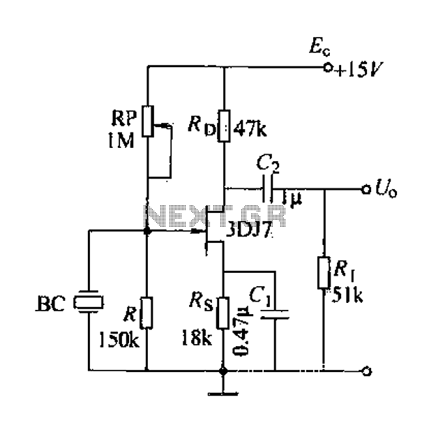
A field effect transistor (FET) voice amplifier has a low input impedance, approximately 1 kΩ, requiring the signal source to provide a constant current signal for operation. Unlike bipolar transistors, FETs are voltage-controlled devices that draw minimal current at...
The aim of this design is to reproduce a Combo amplifier of the type very common in the sixties and the seventies of the past century. It is well suited as a guitar amplifier but it will do a...
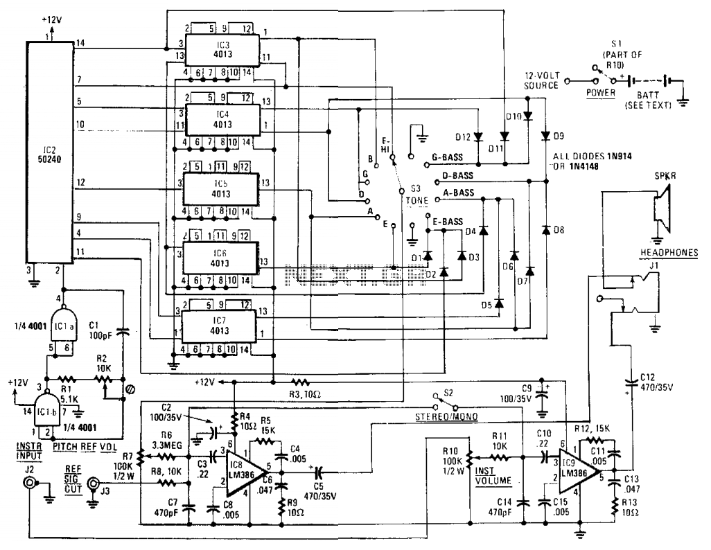
The core component of the circuit is IC2, a 50240 top-octave generator. This device utilizes a single input frequency to produce all twelve notes of the musical scale. The input signal is supplied by IC1, a 4001 quad 2-input...