
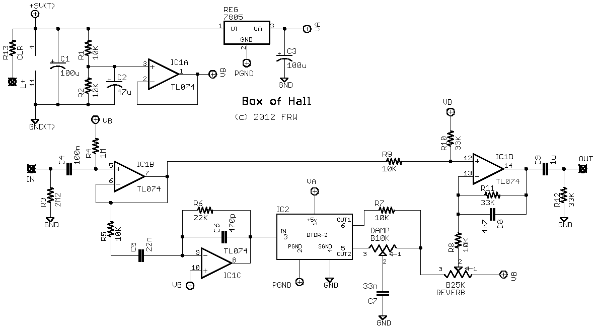
prototype reverb pedal using the accutronicsbelton btdr 2h module
The circuit design process often begins with a clear understanding of the required functionality and the components involved. In this case, the focus is on an op-amp circuit, which is a fundamental building block in analog electronics. Operational amplifiers are versatile components used for various applications, including amplification, filtering, and signal conditioning.
The schematic referenced is likely part of a larger system, where the op-amp plays a crucial role in processing signals. It is important to ensure that the power supply circuitry is adequately designed to meet the voltage and current requirements of the op-amp. This typically involves selecting appropriate voltage regulators or power supply designs that can provide stable and clean power to the op-amp, which is essential for optimal performance.
When designing the power supply for an op-amp circuit, several factors must be considered, including the supply voltage levels, current requirements, and noise considerations. The op-amp may require dual power supplies (positive and negative) for certain configurations, particularly when processing AC signals or when the output needs to swing above and below ground.
In addition to power supply design, understanding the feedback network around the op-amp is crucial. Feedback resistors must be chosen to set the gain of the amplifier while ensuring stability and bandwidth requirements are met. The layout of the circuit on the breadboard should also minimize parasitic capacitances and inductances, which can adversely affect the performance of the op-amp.
For those new to op-amps, it is advisable to start with simple configurations, such as inverting or non-inverting amplifiers, before progressing to more complex applications. Utilizing simulation software can also aid in visualizing circuit behavior before physically assembling the components on a breadboard. This systematic approach will help in gaining a better understanding of operational amplifiers and their applications in electronic circuits.As a follow-on to my previous post about building a breadboard prototyping rig, here`s some information about my first attempt at a circuit. The schematic I found a schematic within the application note for the module itself, on this page but it did not include schematics for the power supply circuitry.
I`m still so new to op-amps.. 🔗 External reference
Related Circuits
This weblog discusses electronic circuit schematics, PCB design, DIY kits, and electronic project diagrams. The rain detector operates on the principle of an astable multivibrator using the 555 timer IC, which is equipped with a sensor capable of detecting...
500 Series immersion temperature probe, NTC, 100,000 Ohm, ±1.5 °C [±2.7 °F] tolerance, 10 °C to 260 °C [50 °F to 500 °F] accuracy, stainless steel, bullet housing, flying leads (two), 26 gauge Teflon insulation, 4,267 mm [168 in]. The...

U1 (555 in monostable mode) generates a square wave signal that corresponds to the input signal. This square wave is then sent to the mixer (U2) along with the original signal for mixing, effectively functioning as a frequency doubler....
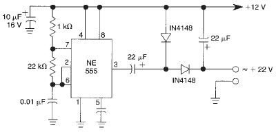
This voltage doubler circuit utilizes a 555 timer integrated circuit configured as an astable multivibrator. It can deliver a maximum output current of 50mA; exceeding this limit will result in a reduction of the output voltage. The actual output...
This circuit employs an HgCdTe demodulation device that can be cooled to 77K using liquid nitrogen. It utilizes a constant current bias for the demodulation device, which is connected to the input port. The voltage amplification factor is 200,...
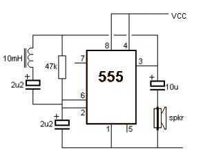
A very simple metal detector electronic project can be designed using a simple 555 timer integrated circuit. As you can see in the schematic circuit, this electronic project requires few external electronic parts. This circuit detects metal and also...