
Guitar treble boost
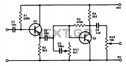
In this circuit, Q1 is utilized as an emitter follower configuration, which is characterized by its ability to maintain a high input impedance while providing a low output impedance. This feature is particularly advantageous in guitar applications, where it ensures that the guitar's signal is not significantly loaded down, preserving the integrity of the sound.
Capacitor C2 plays a critical role in shaping the frequency response of the circuit. Its low capacitance value is strategically chosen to attenuate the lower frequency bass signals, thereby allowing the circuit to focus on higher frequencies that are more relevant for guitar tones. This filtering helps to create a cleaner and more defined sound, especially in scenarios where bass frequencies may muddy the overall tone.
C3, in conjunction with RV1, acts as a tone control mechanism. RV1 is a variable resistor (potentiometer) that adjusts the resistance in the circuit, thereby controlling the amount of treble that is allowed to pass through. By altering the resistance, the user can effectively boost or cut treble frequencies, enabling customization of the tonal characteristics to suit personal preferences or specific musical contexts.
Q2 is introduced as a preamplifier stage, which is essential for recovering any signal losses that may occur due to the filtering effects of C2 and C3, as well as the resistive load introduced by RV1. This preamp ensures that the signal remains strong and clear, providing the necessary gain to drive subsequent stages of the audio signal chain. The design emphasizes the importance of maintaining signal integrity throughout the circuit, allowing for a high-quality audio output that is critical in performance settings.
Overall, this circuit exemplifies a thoughtful approach to guitar signal processing, combining impedance buffering, frequency filtering, and amplification to achieve a versatile and responsive tone control system.Ql is connected as an emitter follower in order to present a high input impedance to the guitar. C2, being a relatively low capacitance, cuts out most of the bass, and C3 with RV1 acts as a simple tone control to cut the treble, and hence the amount of treble boost can be altered. Q2 is a simple preamp to recover signal losses in C2, C3, and RV1. 🔗 External reference
Related Circuits
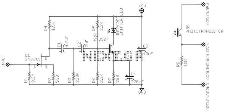
An attempt at an Arduino guitar pedal. The guitar signal feeds through a PT2399 delay circuit, modified to include a JFET preamp phase. The delay circuit has Echo and Delay knobs. From there, it feeds into an optoisolated-Arduino-5V preamp,...
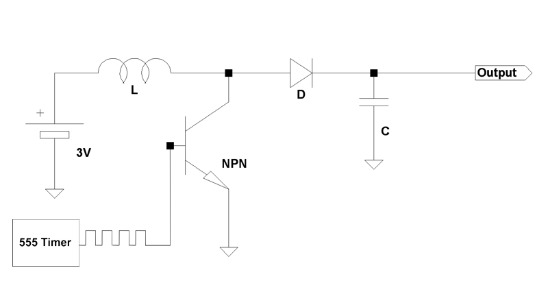
Boost circuits are an effective method for powering microcontrollers. Rather than using multiple AA batteries or a 9V battery (which is typically regulated down to 5V or 3.3V), one can boost the voltage from one or two AA batteries...
In personal electronics and computer audio systems, the SSM2167 is a complete and flexible solution for conditioning microphone inputs. It is also very good for various applications. The SSM2167 is an integrated circuit specifically designed for microphone preamplification and audio...
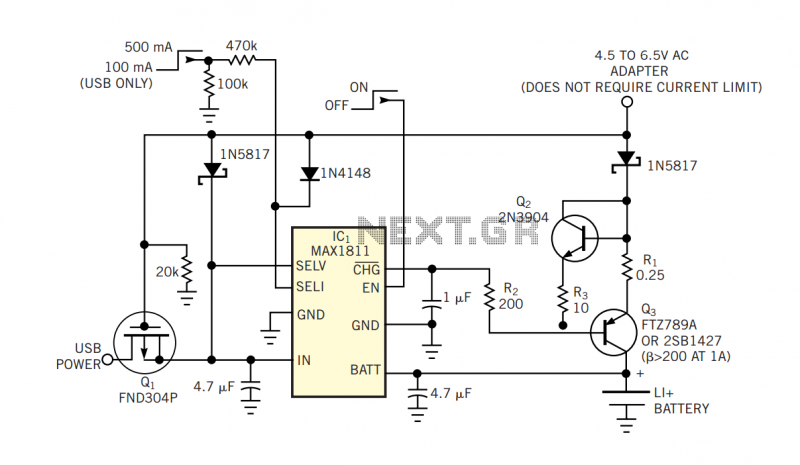
The popular USB interface can charge a portable device while transferring data. But for high-capacity batteries, the 500-mA output current of USB hosts and powered hubs greatly extends the charging time. Thus, a system that accepts charging power from...
In battery-powered applications such as cell phones, PDAs, and digital cameras, an integrated DC-DC converter circuit solution provides multiple advantages regarding cost, size, and design complexity. A significant challenge in achieving a fully integrated solution is designing the frequency...
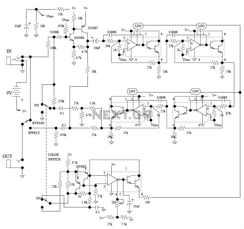
This is the schematic diagram of the Electro-Harmonix Small Stone Phaser guitar effect pedal. The Small Stone is notable for using Operational Transconductance Amplifiers (OTAs) for phase shift stages instead of traditional operational amplifiers. The Electro-Harmonix Small Stone Phaser is...