
Guitar Vibrato circuit
The circuit described consists of a phase shifter utilizing operational amplifiers (op-amps) and field-effect transistors (FETs) to manipulate the phase of an audio signal. The design aims to accommodate the challenges associated with sourcing matched FETs, which are essential for maintaining consistent performance in phase shifting applications. The circuit is structured to work with readily available, off-the-shelf FETs, enhancing its accessibility for practical implementation.
At the core of the circuit is a standard op-amp configuration, which serves as the primary mechanism for phase manipulation. The op-amp is configured in a feedback loop that allows for precise control of the phase shift introduced to the input signal. The choice of FETs in the circuit is critical, as they are employed for their variable resistance characteristics, which are necessary for achieving the desired modulation effects. However, the setup process can be intricate due to the sensitivity of FETs to variations in parameters such as temperature and biasing conditions, which can lead to linearity issues.
The circuit features an EFFECT control, which is a unique aspect that provides flexibility in signal processing. This control allows the user to select between three distinct output options: a clean signal directly from the buffer stage, a fully phase-modulated signal from the output of the second op-amp (U2A), or a blended output that combines both the clean and modulated signals. This capability enables users to tailor the output to their specific needs, whether for pure signal processing or for creative modulation effects.
In summary, the circuit is designed to be conventional in its operation while incorporating an innovative control feature that enhances its functionality. The careful selection of components, particularly the FETs, is essential for achieving the desired performance, making it a useful tool for audio signal processing applications.The circuit of the unit is fairly simple, but is a bit irksome to set up. The reason is that obtaining matched FETs is not easy, so I had to make sure that the circuit would work with off-the-shelf FETs. The phase shifter is a standard opamp circuit, and has been used for this sort of application many times.
After experimenting with alternative variable resistors, I decided that the FET was still the best choice, although they are fairly critical to set up, and have linearity problems. The circuit is conventional, except for the EFFECT control. With this, you can select the clean signal direct from the buffer stage, the fully phase (and hence frequency) modulated signal from the output of U2A, or a mixture of the two. With the pot centr 🔗 External reference
Related Circuits
The Electronic Dazer is a modern, portable, personal-protection appliance. It generates high potential energy to ward off vicious animals or other attackers. It is an aid to help escape from a potentially dangerous situation. The device develops about 2,000...
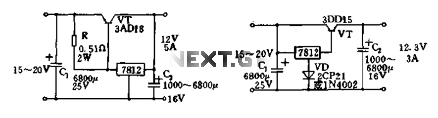
Expand integrated three-terminal regulator block circuit output current method The integrated three-terminal regulator is a versatile component commonly used in power supply circuits to provide a stable output voltage. This regulator typically consists of three terminals: input, output, and ground....
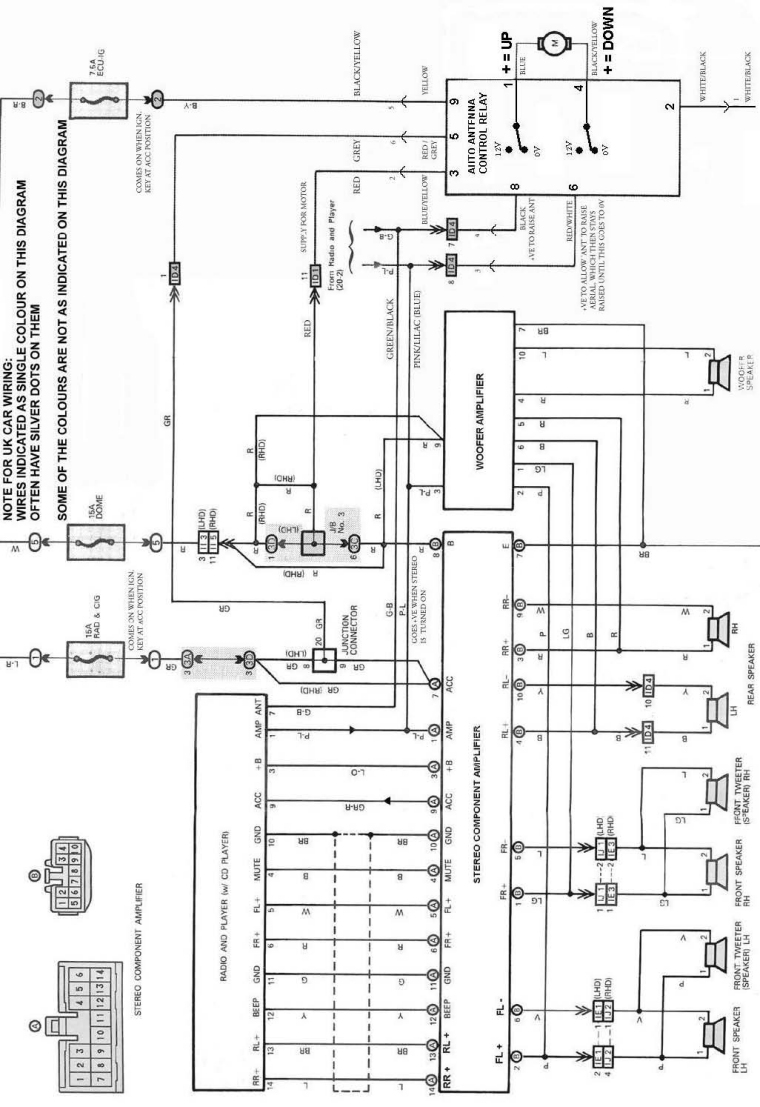
The following circuit illustrates an electrical circuit diagram for the MR2 MKII electric aerial. Features include control by an Aerial Control Relay, which consists of... The MR2 MKII electric aerial circuit is designed to facilitate the automatic operation of the...
DTMF-based Robo Car design using the 8051 microcontroller project. This project demonstrates a method to control a domestic system using the DTMF tone generated by a telephone instrument when the user presses the keypad buttons of a mobile phone...
DC Motor Control Using a Single Switch. This simple circuit allows for the operation of a DC motor in both clockwise and counterclockwise directions, as well as stopping it using a single switch. The circuit utilizes non-latching push button...
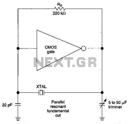
The CMOS amplifier is biased into the linear region by resistor RB. The pi-type crystal network (C1 and C2, and XTAL) provides the 180-degree phase shift at the resonant frequency, which causes the circuit to oscillate. The described circuit utilizes...