
ElectricalCircuit For MR2 MKII Electric Aerial
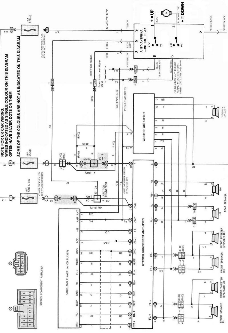
The MR2 MKII electric aerial circuit is designed to facilitate the automatic operation of the aerial system. The circuit includes an Aerial Control Relay that acts as the primary switching component, allowing for the extension and retraction of the aerial based on user inputs or vehicle status. The relay is typically activated by a switch located on the dashboard or through a remote control system.
Key components of the circuit may include a power supply, which provides the necessary voltage for the operation of the aerial motor. The motor is connected to the relay, which serves to control the direction of the motor's rotation. When the relay is energized, it completes the circuit, allowing current to flow to the motor, thereby extending or retracting the aerial.
Additional features may include safety mechanisms such as limit switches that prevent the aerial from overextending or retracting beyond its designed range. These switches can interrupt the power supply to the motor when the aerial reaches its maximum or minimum position, protecting the motor from damage.
The circuit may also incorporate diodes for flyback protection, ensuring that any back EMF generated by the motor when it is turned off does not damage the relay or other sensitive components in the circuit.
Overall, the MR2 MKII electric aerial circuit is a well-designed system that enhances the functionality of the vehicle's aerial, providing convenience and reliability to the user.The following circuit shows about Electrical Circuit Diagram For MR2 MKII Electric Aerial. Features: controlled by an ‘Aerial Control Relay , consisting of .. 🔗 External reference
Related Circuits
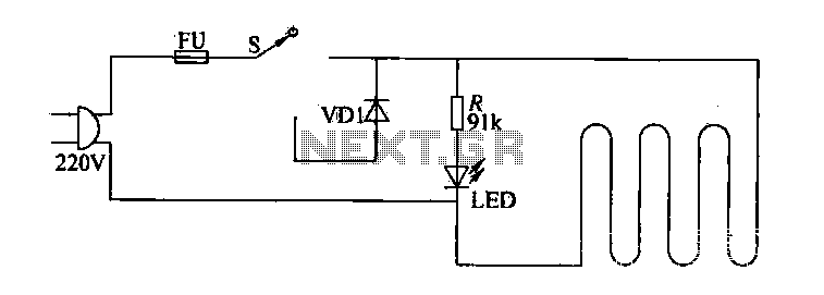
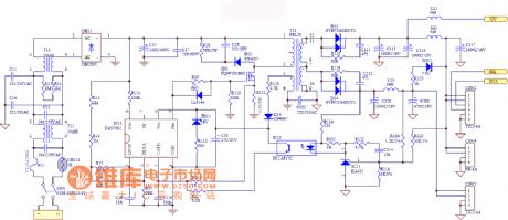
The circuit of electric blankets is controlled by switch S. When switch S is fully engaged, the entire supply voltage of 220V is applied to the heating wire, resulting in a high-temperature state. When a lower temperature is desired,...
A model has been constructed based on the principles of a horizontal steam engine, where the steam cylinder is substituted with an electromagnet featuring a moving core. The construction specifics are less significant, as the accompanying photos provide all...
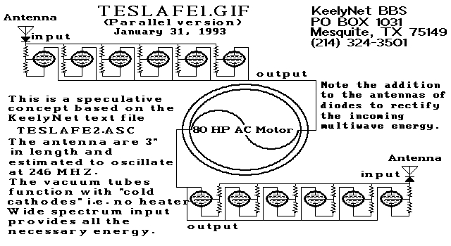
Two schematic diagrams illustrate a series and a parallel circuit configuration that Tesla may have utilized. The components featured are the 70L7GT Half Wave Rectifier tubes, which are surprisingly still available today. While there is an interest in accessing...
This unit captures the ATV signal by sampling the transmission line with minimal insertion loss. It features two N connectors for input and output connections, while a BNC connector is utilized for the video output. The detected output connects...
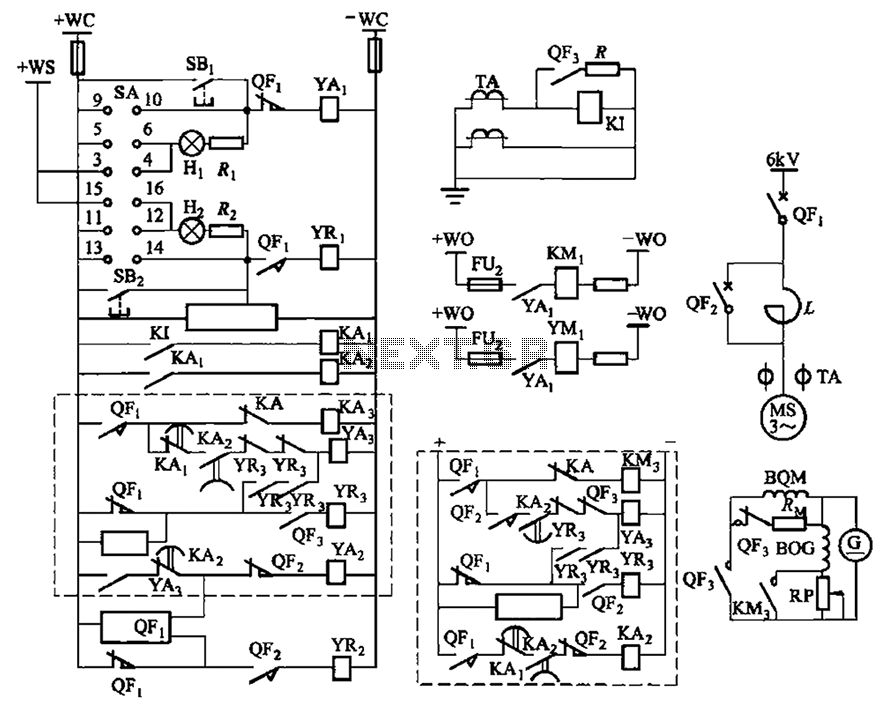
The circuit depicted in Figure 3-189 includes various components such as switch SA, closing button SBi, trip button SBz, de-excitation switch Yaa, and off trip coil YR3. The excitation switch contacts are represented by QF3, which serves as a...
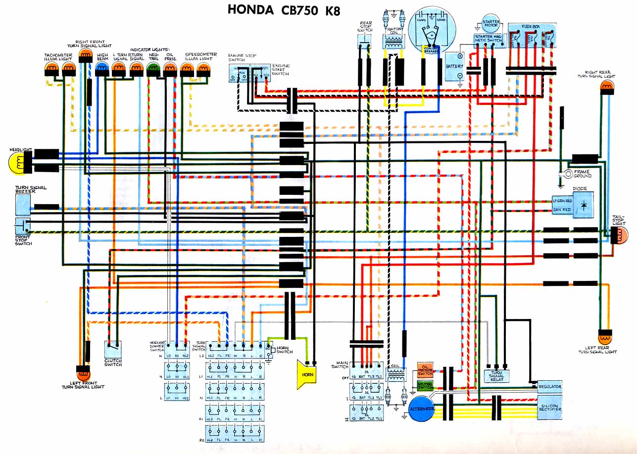
The following circuit illustrates the electrical circuit diagram for the Honda CB750 motorcycle. Features include a turn signal relay, oil pressure switch, and neutral switch. The Honda CB750 electrical circuit diagram is designed to facilitate the understanding and troubleshooting of...