
GVI Digital Remote Control
The GVI Digital Remote Control circuit is designed to enhance the functionality and usability of DSLR cameras by providing an efficient interface for triggering the shutter or flash remotely. The core of the circuit is the ATmega328 microcontroller, which is a popular choice for embedded systems due to its versatility and ease of programming through the Arduino IDE. The microcontroller processes input signals from the sensors, allowing for real-time responses to environmental changes.
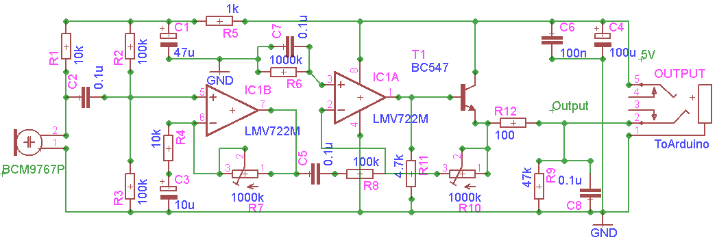
The light sensor integrated into the system is crucial for enabling operation in various lighting conditions. The choice of R1 and R2 resistors is pivotal, as they allow for fine-tuning of the sensor's sensitivity and the overall gain of the circuit. This ensures that the remote control can effectively respond to different levels of ambient light, thereby increasing its reliability in diverse scenarios.
User interaction with the device is facilitated through a combination of a push button and a joystick switch. The push button serves as a menu navigation tool, allowing users to access different settings and configurations. The joystick switch provides intuitive control over the various functions, such as adjusting settings or selecting options within the menu. This design promotes ease of use, especially in dynamic shooting environments where quick adjustments may be necessary.
The visual feedback is provided by a Nokia 6100 display, which offers a clear and concise representation of the current settings and statuses of the remote control. The choice of a 132x132 resolution GLCD with a Philips controller allows for a rich user interface that can display various parameters and information effectively. The integration of the LCD driver, based on established documentation for the Philips PCF8833 and Epson S1D15G00 controllers, ensures compatibility and ease of implementation.
Overall, the GVI Digital Remote Control circuit is a sophisticated solution for photographers seeking to enhance their shooting capabilities through remote operation, with the potential for further expansion and additional sensor integration in future iterations.GVI Digital Remote Control for DSLR camera is a step forward from my previous remote control for Canon EOS 450D. This remote is based on AVR Microcontroller ATmega328 and is programmed using Arduino IDE GVI Digital Remote Control is a tool for photographers to trigger cameras or flashes based on input signals from various sensors - for the momenti use only sound and light inputs, but maybe
in the future i will add more sensors. Thislight sensor gives you a huge amplification of the signal and can be use to trigger in the dark of night or in the day time (not tested yet in a very sunny day). R1 is used to adjust the sensitivity of the circuit while R2 controls the gain (amplification of the input signal).
This unit is controlled using a push button (Menu Function) and a joystick switch (Up, Down, Left, Right and Set functions) and the remote control settings values are displayed on an Nokia 6100 display (132x132 12bits GLCD) with Philips controller. The LCD driver for this controller is based on this documentation can be downloaded from here for Philips PCF8833 controller and here for Epson S1D15G00 controller.
🔗 External reference
Related Circuits
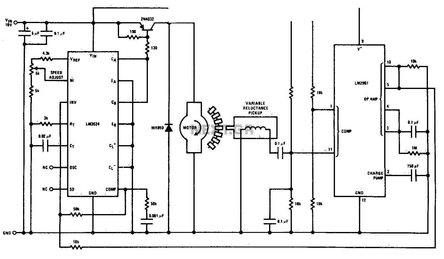
This circuit is a regulating series DC motor speed control using the LM3524 for the control and drive of the motor and the LM2907 as a speed sensor for the feedback network. The circuit employs the LM3524 integrated circuit, which...
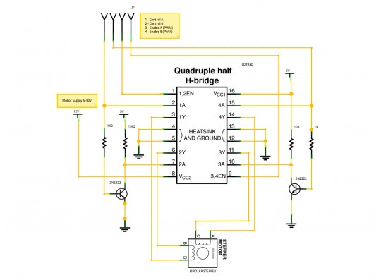
A stepper motor controller based on schematics available on the Arduino website. Initially, a two-pin configuration was attempted for a bipolar stepper motor, but it did not function as expected, especially with the library provided on the site. The...
Today, simplicity and minimal controls are required for the design of a handheld device. It would be very useful if a circuit allows us to turn the power on or off. A handheld device requires an efficient power management circuit...
This DC drill speed controller circuit allows for the adjustment of the rotational speed of a drilling machine. A mini-drill machine is always... This circuit utilizes a pulse-width modulation (PWM) technique to control the speed of a DC motor, which...
This circuit operates at 73 MHz and is designed for controlling halogen lights through radio frequency remote control. The primary function is to toggle the power state of a halogen lamp. When the button on the remote control is...
This circuit automatically controls the headlight of a motorcycle, turning it on and off independently of the light and ignition switches, as long as the battery is fully charged. The initial stage employs a 220-ohm resistor and ZD1 to...