
Motor speed control
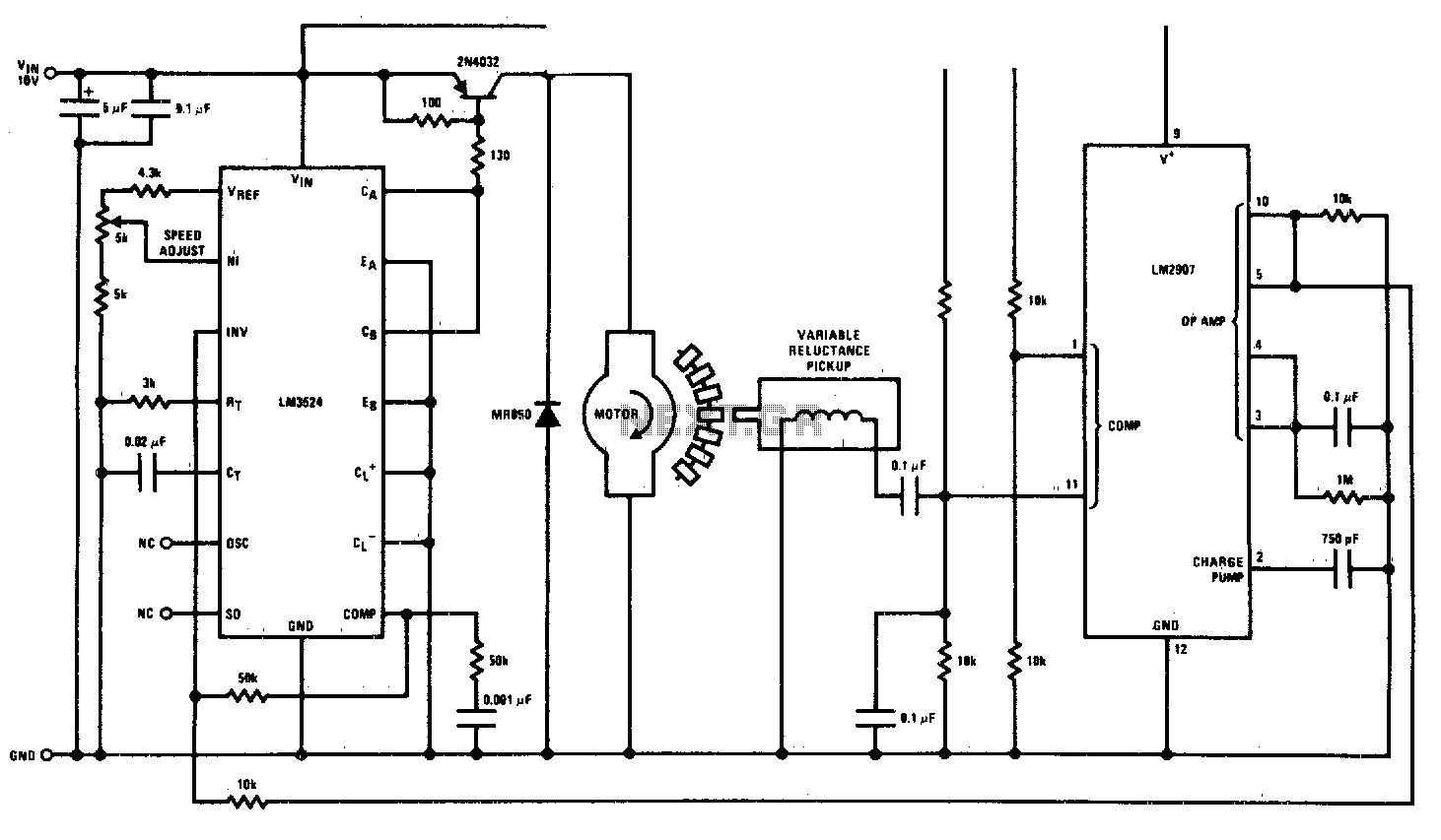
The circuit employs the LM3524 integrated circuit, which serves as both a controller and driver for the DC motor. The LM3524 is a versatile PWM (Pulse Width Modulation) controller that can be utilized to regulate the speed of a DC motor by varying the duty cycle of the output signal. The output from the LM3524 drives a power transistor or MOSFET that controls the voltage supplied to the motor, thus enabling speed regulation.
The LM2907 is used as a speed sensor, providing feedback on the motor's rotational speed. The LM2907 operates as a frequency-to-voltage converter, translating the frequency of the motor's rotation into a proportional voltage. This feedback voltage is then fed back to the LM3524, allowing for closed-loop control of the motor speed. The feedback mechanism ensures that the motor speed can be adjusted dynamically based on the load conditions and desired speed setpoint.
In the schematic, the LM3524 is configured with necessary external components, including resistors and capacitors, to set the PWM frequency and to stabilize the control loop. The use of an appropriate power transistor or MOSFET is crucial for handling the motor's current requirements. The LM2907 is connected to the motor shaft, typically through a gear or a tachometer, to accurately sense the speed of the motor.
Overall, this circuit design provides an effective solution for controlling the speed of a DC motor with high precision and responsiveness, making it suitable for various applications in automation and robotics.This circuit is a regulating series dc motor speed control using the LM3524 for the control and drive for the motor and the LM2907 as a speed sensor for the feedback network. 🔗 External reference
Related Circuits
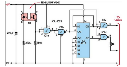
Here is how to build a pendulum-controlled clock that can be made very accurate. Retro? Yes, but it is an interesting project nonetheless. You will need a specific set of components. A pendulum-controlled clock is a mechanical timekeeping device that...
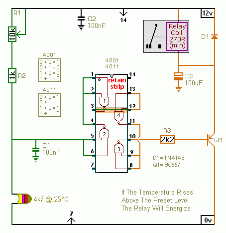
The first circuit energizes the relay when the temperature rises above the preset level. The second circuit energizes the relay when the temperature falls below the preset level. The two circuits are practically identical. The only difference between them...
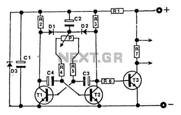
This circuit is designed for controlling motors, lamps, heating elements, and similar devices continuously from nearly zero to maximum capacity (5-95%). It utilizes impulse control for nearly lossless operation, providing almost total torque for motors. The transistor T3 must...
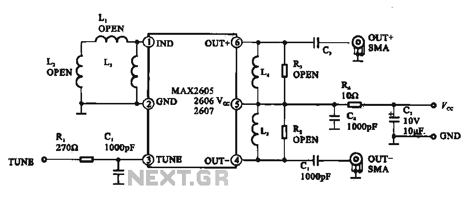
A low phase noise voltage-controlled oscillator circuit is presented, specifically integrated within the MAX2605-2609 voltage-controlled oscillator series. The circuit features a tuning voltage control terminal, allowing for adjustable oscillation frequency through a DC voltage input. The output of the...
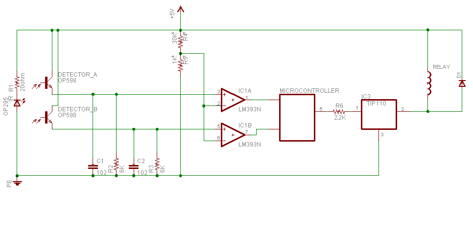
Sensing unit consists of infrared emitter OP295 to produce the infrared beam, and two detectors in front of the emitter to detect the infrared beam OP598. Since the main idea in this device is to know person direction; and...
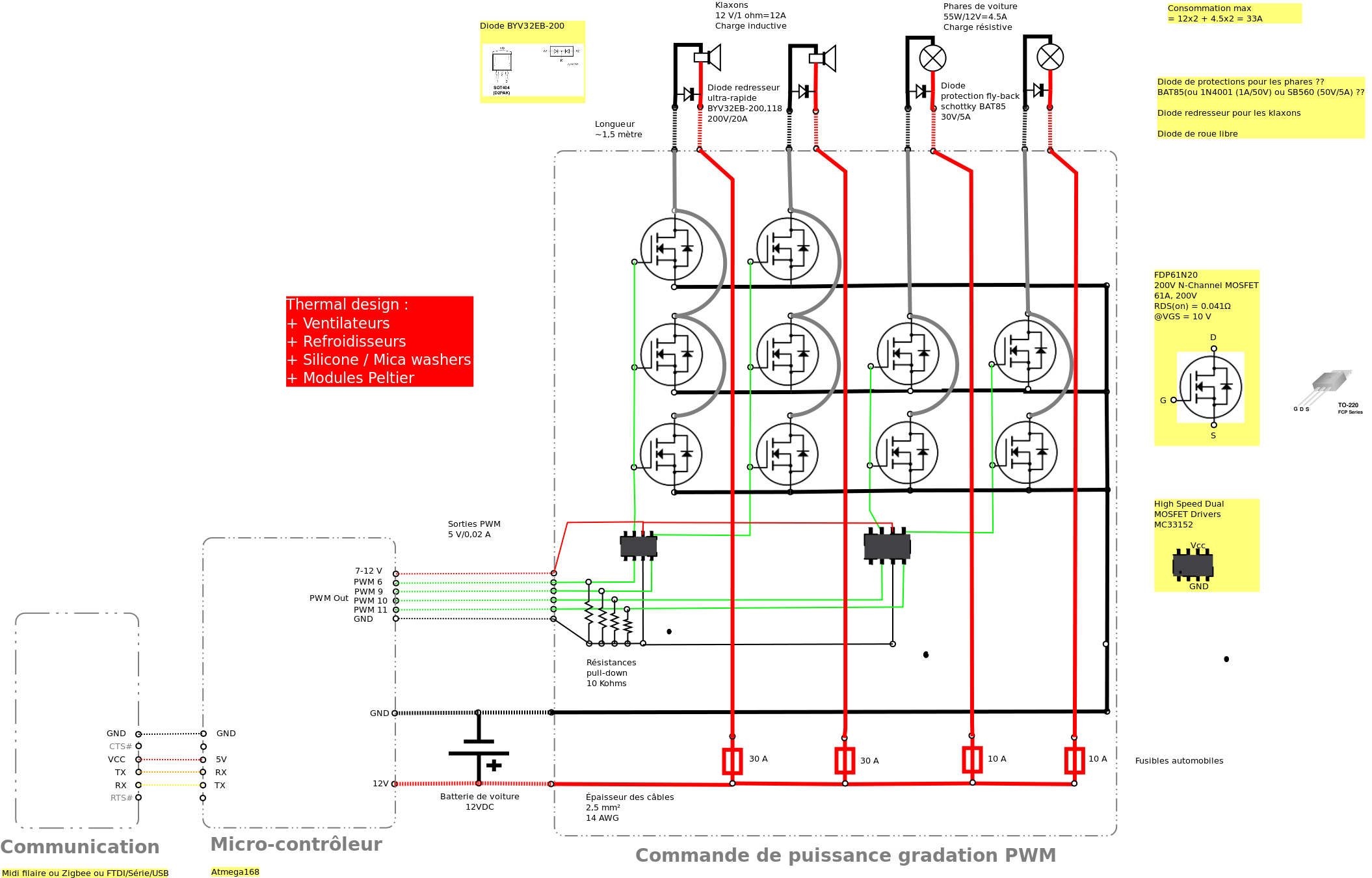
Past experiences were quite challenging due to the inductive nature of car horns, which require 12A of current, with peak demands reaching 20 to 30A. The current electronic system lacks reliability, given the high intensity. There is a need...
Warning: include(partials/cookie-banner.php): Failed to open stream: Permission denied in /var/www/html/nextgr/view-circuit.php on line 713
Warning: include(): Failed opening 'partials/cookie-banner.php' for inclusion (include_path='.:/usr/share/php') in /var/www/html/nextgr/view-circuit.php on line 713