
gym agility simple strategy
This electronic schematic describes a competitive game circuit designed for two players, featuring a strategic interaction between illuminated indicators and user inputs. The core of the circuit is based on a combination of bistable latches and a multiplexer to manage game states and outputs effectively.
The use of Schmitt NAND gate IC1a and IC1b ensures that the game logic remains stable, eliminating issues related to switch bounce that could disrupt the game flow. The bistable latches serve as memory elements, holding the state of each player's LEDs. When a player presses a button, a signal is sent to the corresponding latch, which toggles the state of that latch and simultaneously affects the opposing player's LED.
The multiplexer IC2 is pivotal in determining the game outcome. It monitors the states of the four bistable latches and translates these states into binary form, allowing it to identify winning conditions. The design ensures that only when all four inputs are either high or low does it trigger a win condition, thereby reducing the chances of false positives during gameplay.
In the gym application, replacing the LEDs with N-channel power MOSFETs allows for the control of larger lighting elements, such as 12V globes. This modification enhances the game's physicality and engagement, as players must not only strategize but also physically compete to control the circuit.
The incorporation of timers using IC1c and IC1d adds a necessary pause after a win, preventing immediate re-engagement and allowing players to acknowledge the result. This feature is crucial in maintaining the integrity of the gameplay experience, ensuring that players cannot instantly reset the game without a brief intermission.
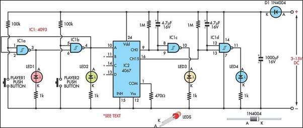
Overall, this circuit design provides an innovative approach to interactive gaming, combining electronic control with physical activity, thereby enhancing user engagement through competitive play.This simple circuit is a two-person game of strategy and speed - and potentially, agility and athletic fitness. Each player has a row of four LEDs before him/her. Beside each LED, there is a push-button which, when pressed, lights up the corresponding LED. The aim of the game is for a player to illuminate all four of their LEDs in a row, in which case the circuit declares a winner. However, there is a catch. As soon as you light one of your own LEDs, the other player`s corresponding LED goes out - and vice versa. The game begins by giving each player two illuminated LEDs. Consider now that this game is scaled up and used in a gym. If the LEDs in the circuit are directly replaced with N-channel power MOSFETs, then 12V globes can be illuminated (a MOSFET`s gate is wired in place of a LED`s anode, the source goes to negative, and the load is wired between the drain and positive).
If four large push-buttons are mounted on one wall and four on another, this could become a game of agility - if not a physical tussle to keep the other player away from critical push-buttons. Schmitt NAND gate IC1a and IC1b (4093) form a simple bistable latch. When one output (pin 3) goes "high", the other output (pin 4) goes "low" and vice versa. The main advantage of using a bistable latch (as opposed to a flipflop) is that it does not suffer from switch bounce.
Four such bistable latches are fed to inputs A-D of IC2. However, for the sake of simplicity, only one of these is shown; ie, IC1a-IC1b. We now need to identify when all four bistable latches go either "high" or "low". This is done using IC2, a 4067 16-channel multiplexer. When inputs A-D are all "low" (binary 0000), this opens decimal channel 0. Conversely, when all are "high" (binary 1111), this opens decimal channel 15. Channels 0 and 15 thus trigger a win for one side or the other, by taking pins 9 or 16 of IC2 "low". Finally, if the game is quite hectic, a win might only last for a fraction of a second before it is lost again. Therefore, IC1c and IC1d are wired as timers, which do not permit any further play until a win has been reported for one or two seconds - either via LED3 or LED4.
During this time, however, the players` buttons may be pressed to reset the game to two LEDs all. 🔗 External reference
Related Circuits

The circuit presented is a simple audio amplifier capable of delivering 12W to an 8 Ohm speaker. The operational amplifier IC TL081 serves as the preamplifier in this design. Alternatively, any operational amplifier with compatible power supply ratings can...
This simple circuit allows the use of an oscilloscope as a Time Domain Reflectometer (TDR). The operation involves sending a pulse down a cable and observing the resulting reflections. The circuit design for utilizing an oscilloscope as a Time Domain...
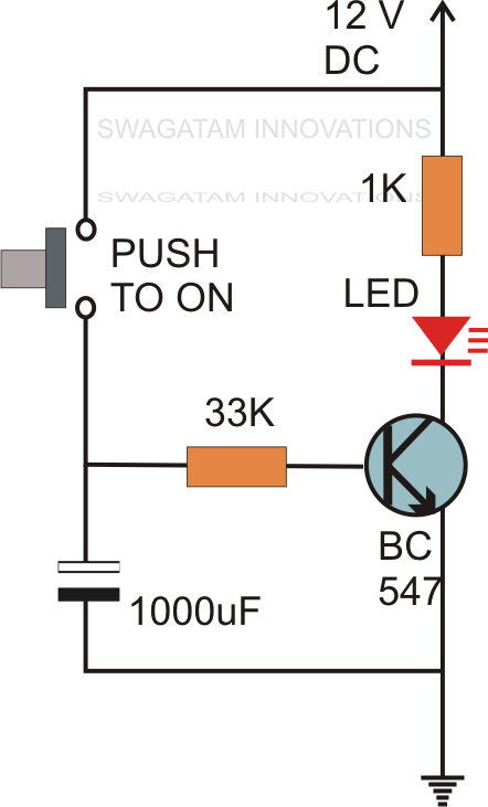
Without the specified delay, the circuit could malfunction or even sustain damage. A capacitor, which is a crucial component of the circuit, is positioned at the other end of the base resistor rather than directly connected to the base...
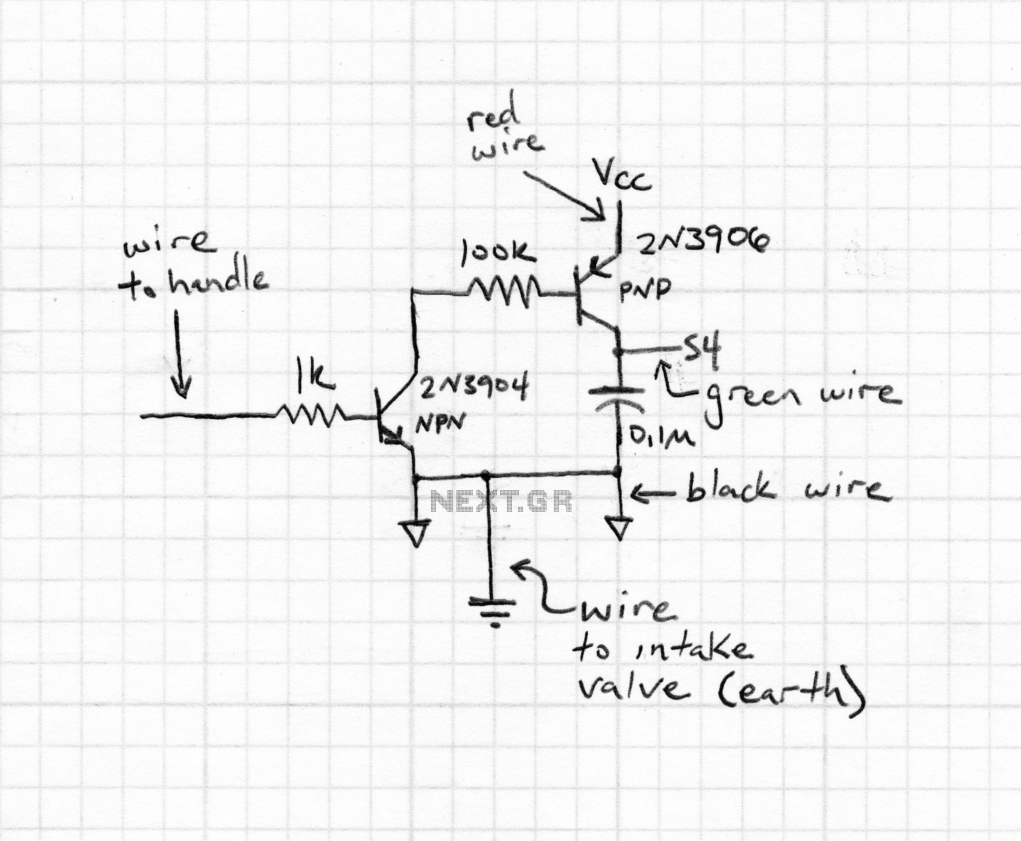
The apparatus consists of a cavers point detection circuit and a triggering display circuit. The cavers instrument functions as a test probe, which, when held in one hand, can detect acupuncture points by touching the skin with another probe....
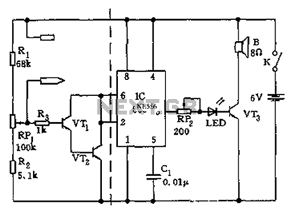
LED 1 will light and the buzzer turns on when the coil is changing inductance. The setup is easy, VR1 is adjusted (away from any metal objects) so that LED 1 will light and the buzzer sounds on, and...
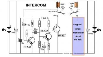
This is a two-station simple intercom circuit built using transistors and common 8-ohm mini speakers. The speaker functions as a microphone and generates sound, eliminating the need for a separate microphone in this intercom setup. The "press-to-talk" switches should...