
Gyraf Audio EQ
The redrawn schematic begins with a standard debalancing input buffer that converts the balanced input signal to unbalanced, feeding into a series of four amplifiers, each connected to its respective filter section, and finally rebalancing the output. The four inverting add/subtract amplifiers operate in series, with the filter inputs connected to either the stage input (at maximum boost) or the inverted stage output (at maximum cut). When the dB+/- pots are centered, the normal and inverted signals cancel each other out, resulting in no signal being applied to the filter section input. The outputs from the filter sections are combined with the inverting inputs of the amplifier stages, effectively boosting or cutting any frequency that the filter sections allow through.
The four filter stages employ standard state-variable filters, with frequency control provided by a 2x100K negative logarithmic potentiometer, which is the only component that may be challenging to procure. The "Q" factor is switchable between high and low, with the switching also controlling filter gain to maintain a constant gain-versus-Q relationship. The "Shelving" switches on the low and high ends also bypass the "Q" switch. The PCB design for the PQ1549 consists of two 100x160mm eurocard PCBs that are interconnected. These single-sided PCBs accommodate all switches and pots, minimizing wiring to input, output, and power supply connections. The artwork files are in PDF format to preserve scale. It is important to note that the PCB (copper) side is drawn in a mirrored format to facilitate closer printout-to-photoresist contact during PCB fabrication. In case of uncertainty, the text on the board should serve as a reference.This pages contain information about building your own version of the Calrec PQ1549 Equalizer, the one found in the Calrec "Polar" desk. This EQ is one of my absolute favorites when it comes to standard IC-based types, so I made this project to make it possible for more people to experience these qualities.
I will try to update this page reguarly if anyone shows interest in its topics. Comments and corrections are welcome, but I can`t promise to reply to all mail. If you do this project and describe the process on your webpage, I`ll be more than happy to add a link here, so others can benefit from your experiences. Notice that all information, schematics, layouts etc. are supplied "as is", and that we can in no way be held responsible for its acurateness, functionality or even safety.
Gyraf Audio shall not be responsible and disclaims all liability for any loss, liability, damage (whether direct or consequential) or expense of any nature whatsoever which may be suffered as a result of or which may be attributable, directly or indirectly, to the use of or reliance upon any information, links or service provided through this website. Also you should take extreme caution when working with mains voltages. These voltages are lethal, and the smallest error will be chatastrophic. And we like you to stay alive and well, so you can help other people sharing our bizarre interest for building retro-pro-audio-equipment.
The Calrec PQ1549 is a classic no-nonsense parametric equalizer from the famous (and huge!) Calrec "Polar" desk, that were only manufactured in very small numbers. I believe that there`s less than 15 desks like this left worldwide. This is an adaption of the original Calrec PQ1549 module to components and parts that are available (hopefully) everywhere.
Adaption includes removal of the mic preamp, filters and switching, changing to newer and even better opamps, adding electronically balanced input and output and a hardwired bypass switch. No doubt that some of you would have liked the Micamp and all, but these imply quite a few not-so-easy-to-get components.
So I`m going for the raw EQ section. Looking on the redrawn schematic, we first have a standard debalancing input buffer, converting our balanced input signal to unbalanced, and feeding a series of four amplifiers connected one to each` own filter section, and finally balanced again for the output. The four inverting add/subtract amplifiers - working in series - has the filters` inputs connected to either the stage input (at max.
boost) or to the inverted stage output (at max cut). Keeping in mind, that the output from each stage is a inverted replica of the input, it`s easy to see that when the dB+/- pots are in their centre positions, the normal and inverted signals cancels out, and no signal is applied to the filter section input. The output from the filter sections are added in with the inverting inputs of the amplifier stages, effectively boosting or cutting any frequency that the filter sectionlets through.
The four filter stages are - more or less - standard state variable filters. Their frequency is controlled by a 2x100K negative logaritmic potentiometer, which is the only "hard to get" component in this design. The "Q" factor is switchable high or low, the switching also controlling filter gain to acheive a constant gain-versus-Q.
The "Shelving" switches on the low and high end also bypasses the "Q" switch. The PCB set for the PQ1549 consists of two 100x160mm "eurocard" pcb`s, that are interconnected. The PCB`s are single-sided, and carry all switches and pots, limiting wireing to input, output and PSU. The artwork files are in PDF format to maintain scale. Please note that the PCB (copper) side is drawn MIRROR`ED - enabling closer printout-to-photoresist contact when making the PCB.
If in doubt, use the text on the board as reference. 🔗 External reference
Related Circuits
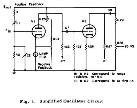
After repairing several Hewlett Packard vacuum tube voltmeters, research was conducted on the company's history. An HP-200C oscillator was located, which closely resembles the company's initial product. It is a Wien bridge resistance-tuned oscillator featuring a light bulb stabilized...
The total electric current drawn by the circuit should be measured by connecting the probes of a multimeter across the positive output of the power supply and the positive rail input of the amplifier. The expected current value is...
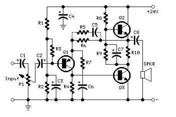
The sound system features a de-sensitized design with a maximum range that can be increased if desired. It includes two tone controls: one offering a lift of 10 dB and the other providing a subtle cut of 3 dB....
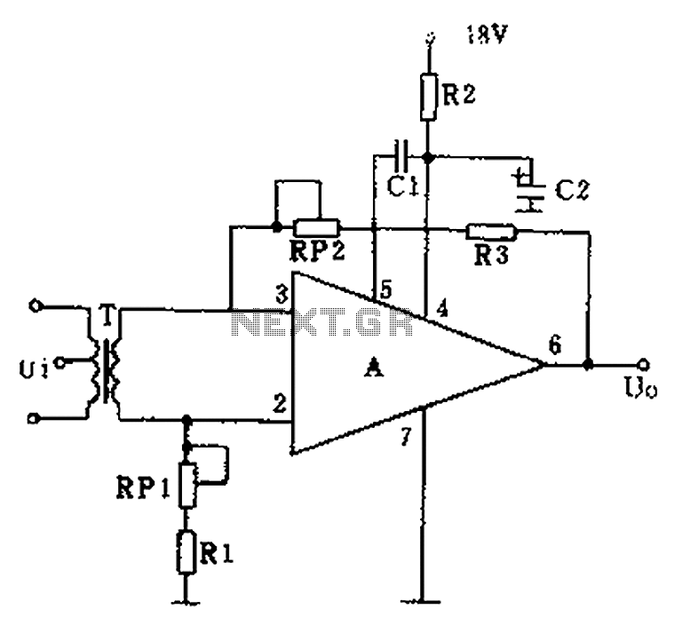
The operational amplifier A is utilized in an audio preamplifier circuit. Its advantages include compact size, low noise, low power consumption, and excellent consistency. The operational amplifier can achieve significant negative feedback while increasing output without distortion. The signal...
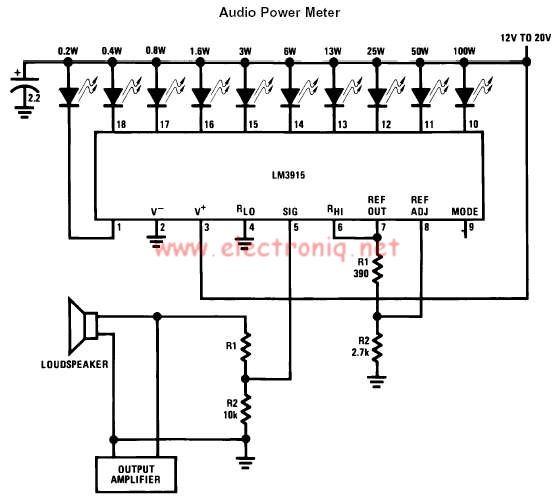
The LM3915 monolithic integrated circuit can be used to design a simple audio power level meter that senses analog voltage levels and drives ten LEDs, LCDs, or vacuum fluorescent displays, providing a logarithmic 3 dB/step analog display. One pin...
The example below illustrates the use of an operational amplifier (op-amp) as an audio amplifier in a basic intercom system. A small 8-ohm speaker is utilized as a microphone, which is connected to the op-amp input through a 0.1...