
GF2A op amp audio amplifier circuit diagram
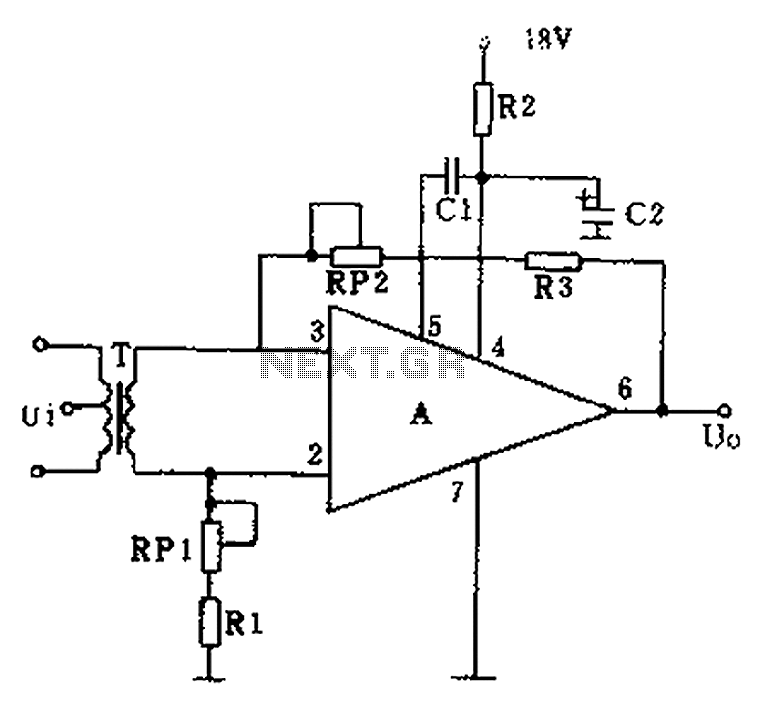
The audio preamplifier circuit employs an operational amplifier (op-amp) configured for optimal performance in audio applications. The op-amp's design ensures minimal signal distortion, making it suitable for high-fidelity audio systems. The negative feedback mechanism is crucial for maintaining linearity and reducing harmonic distortion, which is particularly important in audio signal processing.
In the circuit, the high-frequency compensation capacitor C1 helps to stabilize the amplifier by controlling the frequency response, preventing unwanted oscillations. The decoupling filter, consisting of C2 and R2, serves to filter out noise from the power supply, ensuring that the op-amp receives a clean voltage supply, which is vital for maintaining audio quality.
The adjustment potentiometer RP1 is used to fine-tune the CMRR, allowing the circuit to effectively reject noise and interference that may affect the audio signal. This is particularly beneficial in environments with significant electromagnetic interference. The second potentiometer, RP2, is integral to the feedback loop, enabling the user to adjust the gain of the amplifier, thus tailoring the output level to match the requirements of subsequent audio processing stages or amplifiers.
The component values specified in the design are selected to optimize performance while keeping the circuit compact. For instance, the choice of capacitors and resistors directly influences the frequency response and gain characteristics of the amplifier. The operational amplifier GF2A is selected for its favorable specifications, including low noise and high gain, making it well-suited for audio applications.
Finally, the use of a small output transformer commonly found in crystal tube radios enhances the circuit's compatibility with various audio sources, ensuring efficient signal transfer and minimizing losses. Overall, the design of this audio preamplifier circuit combines advanced electronic principles with practical component selection to achieve high-quality audio amplification. As shown, the use of the operational amplifier A for audio preamplifier circuit. The advantage is small size, low noise, low power consumption, good consistency. A operational amplifier can achieve a deep negative feedback, while increasing output without distortion. The signal distortion below 1%; voltage gain of the amplifier up to 50 ~ 80dB. Wherein, cl is the high frequency compensation capacitor, c2, R2 decoupling filter circuit. Adjustment potentiometer RPl balances CMRR. Potentiometer RP2 negative feedback element. RP2 adjust the output level can be changed. Component selection: capacitance cl as 82P, c2 to 100p/25v. Resistor R1 is 27kn, R2 is 100n, R3 is 50kn. Potentiometer RPl10kn, RP2 is 100kn. Integrated operational amplifier A with GF2A. Transformer T with Crystal Hugh tube radios commonly used small output transformer instead.
Related Circuits
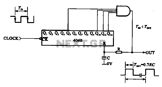
This document illustrates the application of a CMOS integrated circuit (IC) count divider, specifically the TC4040, which functions as a 12- or 14-bit counter. The circuit can be configured to achieve various frequency division ratios, such as a 1:3600...
This circuit is similar to the previous one but employs positive feedback to enhance the amplitude delivered to the speaker. It is adapted from a small 5-transistor radio that utilizes a 25-ohm speaker. In the earlier circuit, the load...
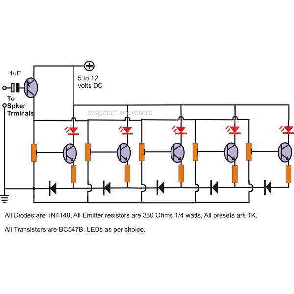
The LEDs in the circuit light up sequentially and "dance" in response to the music level applied at the input, preferably from the speaker terminals of the audio device being monitored. This configuration is consistent across all LEDs in...
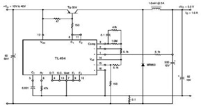
The circuit illustrates a TL494 pulse width modulated step-down converter schematic. This circuit allows for testing of line regulation, load regulation, output ripple, short circuit current, and efficiency under various input voltage conditions. A detailed table of these tests...
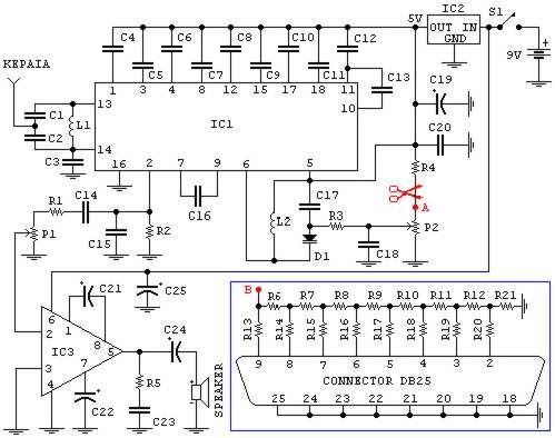
If familiar with programming languages such as C++, PASCAL, VISUAL BASIC, or DELPHI, it is possible to write a program that sends numbers from 0 to 255 through the parallel port (378 I) of a PC. This process checks...
This FET audio mixer demonstrates the versatility of FETs. Originally designed for high-frequency applications, FETs can also effectively handle audio frequencies, showcasing exceptional performance in this domain. The circuit can accommodate an unlimited number of inputs, provided that the...