
LM3915 audio power level meter circuit design electronic project
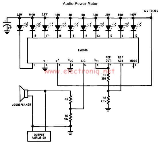
The LM3915 is a versatile integrated circuit specifically designed for audio power level metering applications. This device can accurately sense analog voltage levels, translating these signals into visual representations via ten output channels that can drive various display types, including LEDs, LCDs, or vacuum fluorescent displays. The logarithmic scaling of the output allows for a 3 dB per step indication, which is particularly useful in audio applications where power levels can vary significantly.
The functionality of the LM3915 includes the ability to configure the display mode through a specific pin. This feature allows the user to switch between a bar graph representation and a moving dot display, providing flexibility in the visual output according to user preference or application requirements. The choice between these two modes can enhance the interpretability of the audio levels being monitored.
One of the key advantages of utilizing the LM3915 is its regulated and programmable LED current drive. This feature eliminates the need for external current limiting resistors, simplifying the circuit design and enhancing reliability. The absence of resistors reduces the component count and potential points of failure, making the overall system more robust.
The transition from traditional analog meters to an LED bar graph display offers several benefits. The LED display is not only faster in response time but also more durable and visible under various lighting conditions. This increased visibility aids in the quick interpretation of audio levels, which is critical in live sound environments or monitoring applications.
Furthermore, the brightness of the LEDs can be easily adjusted using a single potentiometer, allowing for customization based on the ambient lighting conditions or user preferences. This adjustability ensures that the display remains effective and comfortable to view over extended periods, enhancing the user experience in practical applications. Overall, the LM3915 integrated circuit provides a powerful and efficient solution for audio power level metering with modern display technologies.using the LM3915 monolithic integrated circuit can be designed a very simple audio power level meter that senses analog voltage levels and drives ten LEDs, LCDs or vacuum fluorescent displays, providing a logarithmic 3 dB/step analog display. One pin of the LM39145 changes the display from a bar graph to a moving dot display. LED current drive is regulated and programmable, eliminating the need for current limiting resistors. Replacing conventional meters with an LED bar graph results in a faster responding, more rugged display with high visibility that retains the ease of interpretation of an analog display. LED brightness is easily controlled with a single pot. 🔗 External reference
Related Circuits
This audio noise filter circuit is a bandpass filter designed for the audio frequency range. It effectively filters out unwanted signals that fall below or above the audio frequency spectrum. The audio noise filter circuit operates as a bandpass filter,...
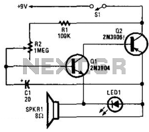
Two complementary transistors create a basic oscillator with a frequency range of approximately 0.5 to several Hz. This circuit serves as a metronome, timer, or pacer for exercise equipment. The oscillator circuit utilizes a pair of complementary transistors, typically one...
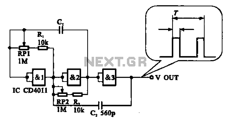
An adjustable pulse generator circuit is presented, which produces a periodic signal with independently adjustable pulse widths. The electrical path allows for modifications to the signal period through the adjustment of RP1. Additionally, RP2 can be altered to change...
The circuit on this page is for a simple light detector circuit board that has 8 detectors that can be used with visible or infrared light systems. The detectors use LM339 voltage comparators as the active element. Phototransistors or...
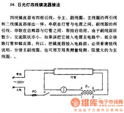
The four-wire ballast connection of a fluorescent lamp consists of four lead wires, which include main and auxiliary coils. The connection of the two lead wires in the main coil is similar to that of a second-line ballast; both...
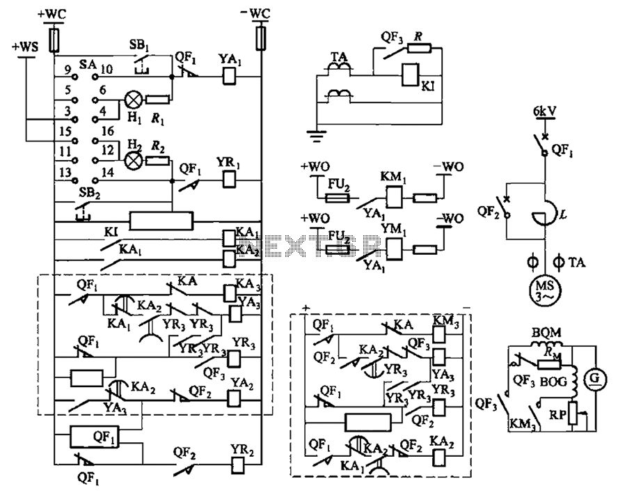
The circuit depicted in Figure 3-189 includes various components such as switch SA, closing button SBi, trip button SBz, de-excitation switch Yaa, and off trip coil YR3. The excitation switch contacts are represented by QF3, which serves as a...
Warning: include(partials/cookie-banner.php): Failed to open stream: Permission denied in /var/www/html/nextgr/view-circuit.php on line 713
Warning: include(): Failed opening 'partials/cookie-banner.php' for inclusion (include_path='.:/usr/share/php') in /var/www/html/nextgr/view-circuit.php on line 713