
Gyrator Circuit

Gyrators serve a critical role in the design of DC holding circuits within Data Access Arrangements (DAAs). These circuits are essential for maintaining the integrity of the connection when the telephone is off-hook. The primary challenge arises from the use of dry transformers, which are unsuitable for DC current due to their construction. To address this limitation, a gyrator can be employed as a viable alternative.
In the circuit design, resistors R1 and R2 are carefully selected to regulate the flow of DC current, ensuring that it remains within the desired parameters. Capacitor C1 acts as a high-pass filter, effectively attenuating any high-frequency signals that may interfere with the operation of the circuit. The design incorporates transistor Q1, whose base-emitter current is maintained at a constant level. This stability is crucial as it directly influences the output of transistor Q2, which is designed to provide a consistent output regardless of fluctuations in the input signal.
The gyrator's unique properties allow the circuit to behave inductively, effectively blocking high-frequency signals while permitting the necessary DC current to flow. This characteristic is particularly advantageous in telephone applications where signal integrity is paramount. Furthermore, the bridge configuration included in the design guarantees that the circuit operates correctly, regardless of the input polarity. This feature is significant in telephone systems, where the tip and ring connections can be inadvertently reversed.
Overall, the integration of gyrators in DC holding circuits not only enhances performance but also ensures reliability in telecommunications applications. The careful selection of components and the thoughtful design of the circuit contribute to its effectiveness in managing DC currents while maintaining signal integrity.Gyrators find application in DC holding circuits which are used in most DAAs (Data Access Arrangements). DAAs typically use dry transformers which can not tolerate DC current, and incorporate a DC blocking cap.
When the telephone goes off hook, it must pass DC current, and so an inductor can be used, which defeats the purpose of using a dry transformer, or a gyrator can be used. R1 and R2 are adjusted so that just the right amount of DC current flows. C1 creates a filter which attenuates any high frequencies to the base of Q1. Since the base to emitter current of Q1 is held constant, output of Q2 is held constant and the circuit looks inductive because it doesn`t pass high frequencies. The bridge is to guarantee that the circuit is powered with the correct polarity, regardless of the input polarity.
Tip and ring on a telephone circuit can often be reversed. Do you need help with an electronics design Daycounter provides contract electronics design services. Contact us to give you a quote on your electronics design project. 🔗 External reference
Related Circuits
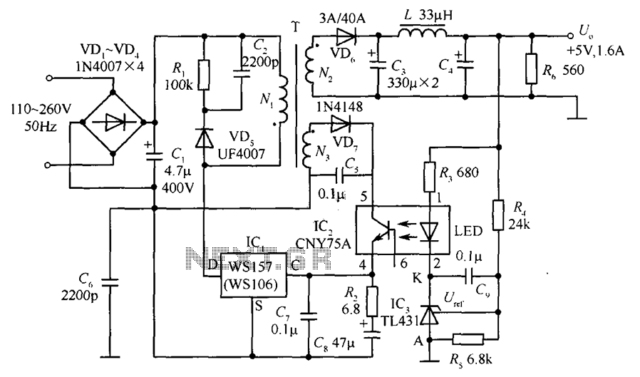
The circuit incorporates an optical coupler (CNY75A) and an adjustable precision shunt regulator (TL431). It includes current limiting resistors R3, R4, and R5 for the sampling resistor. As the output voltage (Uo) varies, the voltage across the sampling resistor...
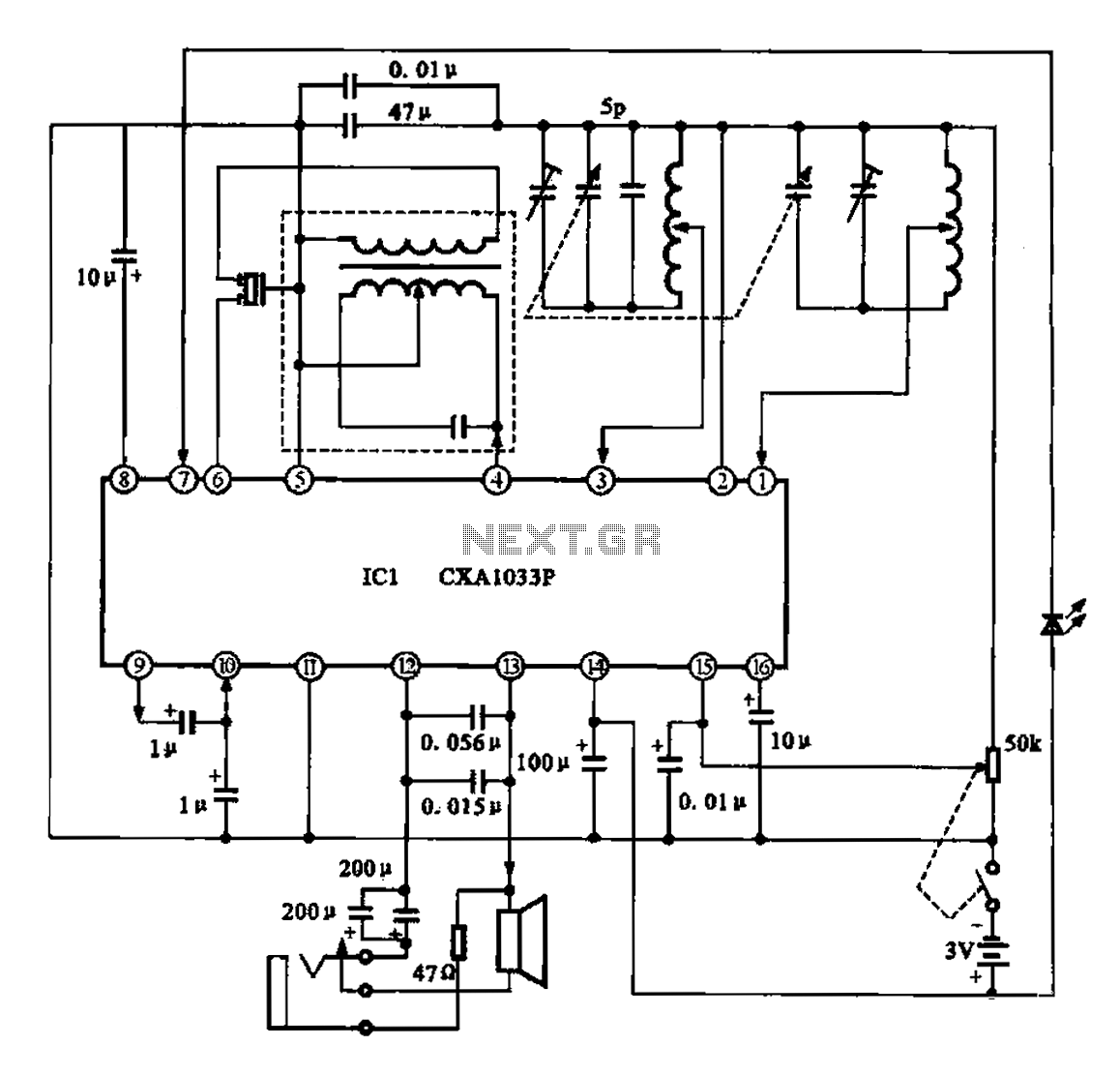
The AM radio features a monolithic circuit design. The broadcast signal is received by an antenna, which feeds into a high-efficiency mixer. The output from the intermediate frequency (IF) transformer undergoes filtering before being sent to the IC1. The...
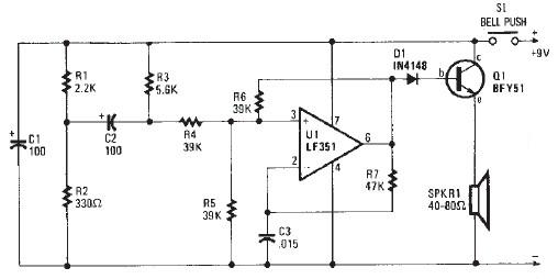
This electronic door buzzer circuit schematic has a straightforward function and is simple to construct. The circuit employs an LF351 operational amplifier along with a few common electronic components. When the S1 push-button is pressed, a positive voltage is...
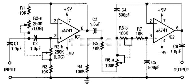
This circuit is a variable audio bandpass filter that features a low cutoff adjustable from approximately 25 Hz to 700 Hz and a high cutoff adjustable from 2.5 kHz to over 20 kHz. The roll-off is set at 12...
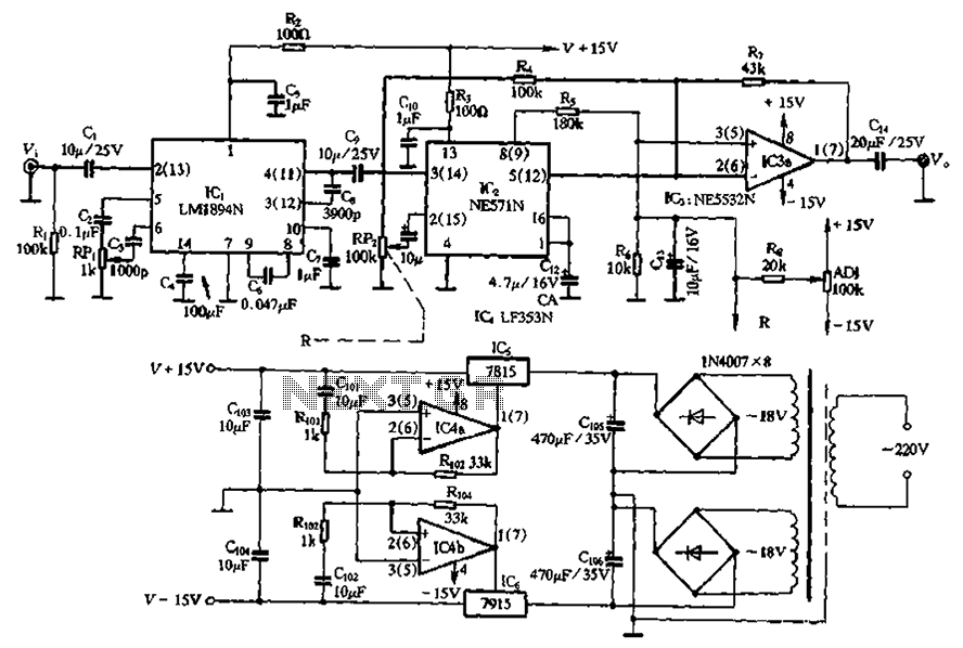
The NE571 and LM1894N form a dynamic expander circuit that enhances performance. This dynamic expander utilizes a variable bandpass filter with the LM1894N. It is particularly effective for dynamic expansion, requiring an RMS rectifier to mitigate noise modulation effects,...
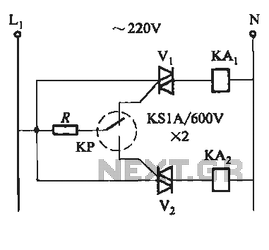
To prevent the failure of electric contact pressure thermometer contacts due to singeing, it is advisable to enhance the contacts, as illustrated in Fig. 11-60. Specifically, the output termination table for DC control utilizes two two-way thyristors or a...