
Variable Bandpass Audio Filter Circuit
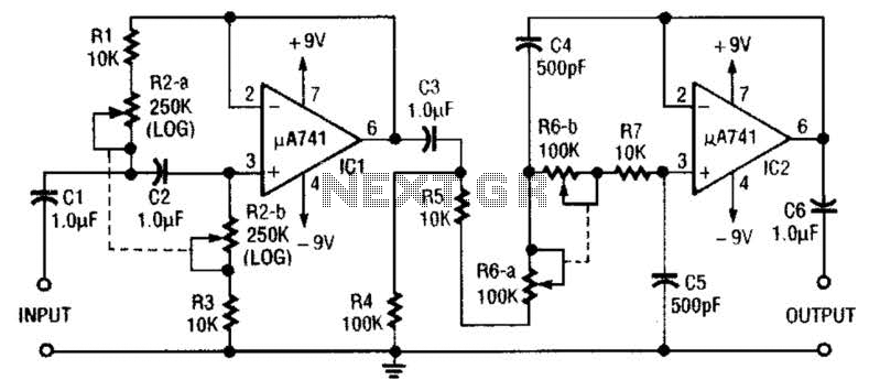
The described variable audio bandpass filter circuit utilizes two ganged potentiometers, R2-a-b and R6-a-b, to allow for precise control over the frequency response. The low cutoff frequency range from 25 Hz to 700 Hz is achieved by adjusting R2, which effectively determines the lower limit of the audio spectrum that will be allowed to pass through the filter. This is particularly useful in audio applications where it is necessary to eliminate low-frequency noise or rumble while preserving the desired audio signals.
Similarly, R6-a-b is responsible for adjusting the high cutoff frequency, which ranges from 2.5 kHz to over 20 kHz. This adjustment enables the filter to selectively allow higher frequency audio signals to pass while attenuating frequencies above the set threshold. The 12 dB/octave roll-off characteristic on both ends ensures a gradual decline in signal amplitude outside the designated frequency bands, preventing abrupt changes that could introduce distortion or unwanted artifacts into the audio signal.
In practical applications, this bandpass filter can be employed in various audio processing scenarios, such as in equalizers, synthesizers, and sound reinforcement systems, where control over specific frequency ranges is essential. The use of ganged potentiometers allows for simultaneous adjustment of both cutoff frequencies, maintaining the desired bandwidth of the filter while ensuring ease of use for the operator. The design can be further enhanced by incorporating additional components, such as operational amplifiers for buffering and gain control, or capacitors for fine-tuning the filter characteristics. Overall, this circuit represents a versatile solution for audio signal processing, enabling tailored frequency response for diverse applications. This circuit is a variable audio bandpass filter that has a low cutoff variable from about 25 Hz to 700 Hz and a high cutoff variable from 2.5 kHz to over 20 kHz. Rolloff is 12 dB/octave on both high and low ends. R2-a-b and R6-a-b are ganged potentiometers for setting lower and upper cutoff frequencies, respectively. 🔗 External reference
Related Circuits
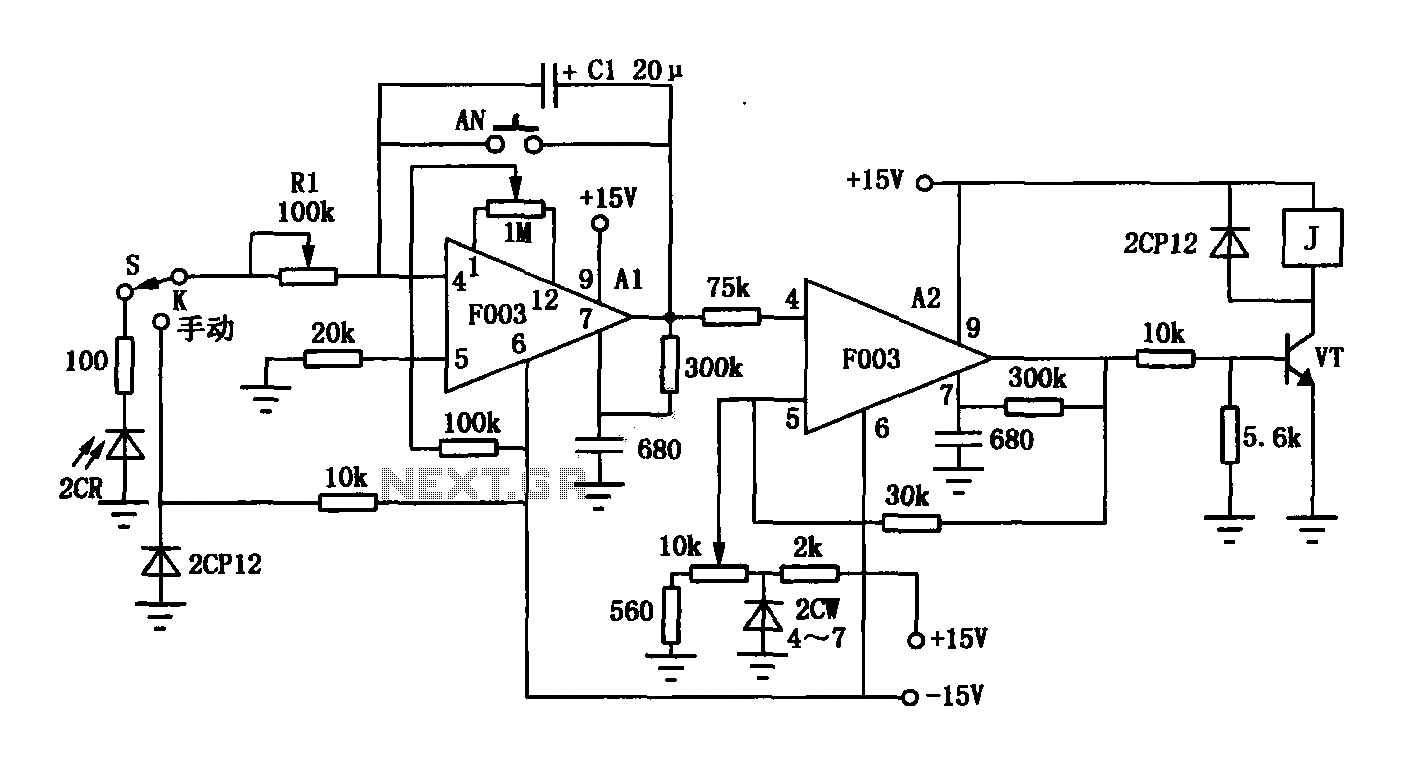
The F003 circuit is a versatile photographic component that functions as an operational amplifier amplifying automatic timer circuit. The operational amplifier A1 serves as an integrator, while operational amplifier A2 is configured as a comparator. A 2CR silicon photocell...
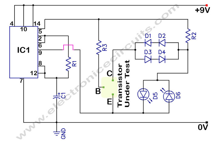
In a circuit transistor tester schematic, there is a circuit that can indicate the condition of a transistor using two LEDs. A good NPN transistor... The circuit transistor tester is designed to evaluate the functionality of both NPN and PNP...
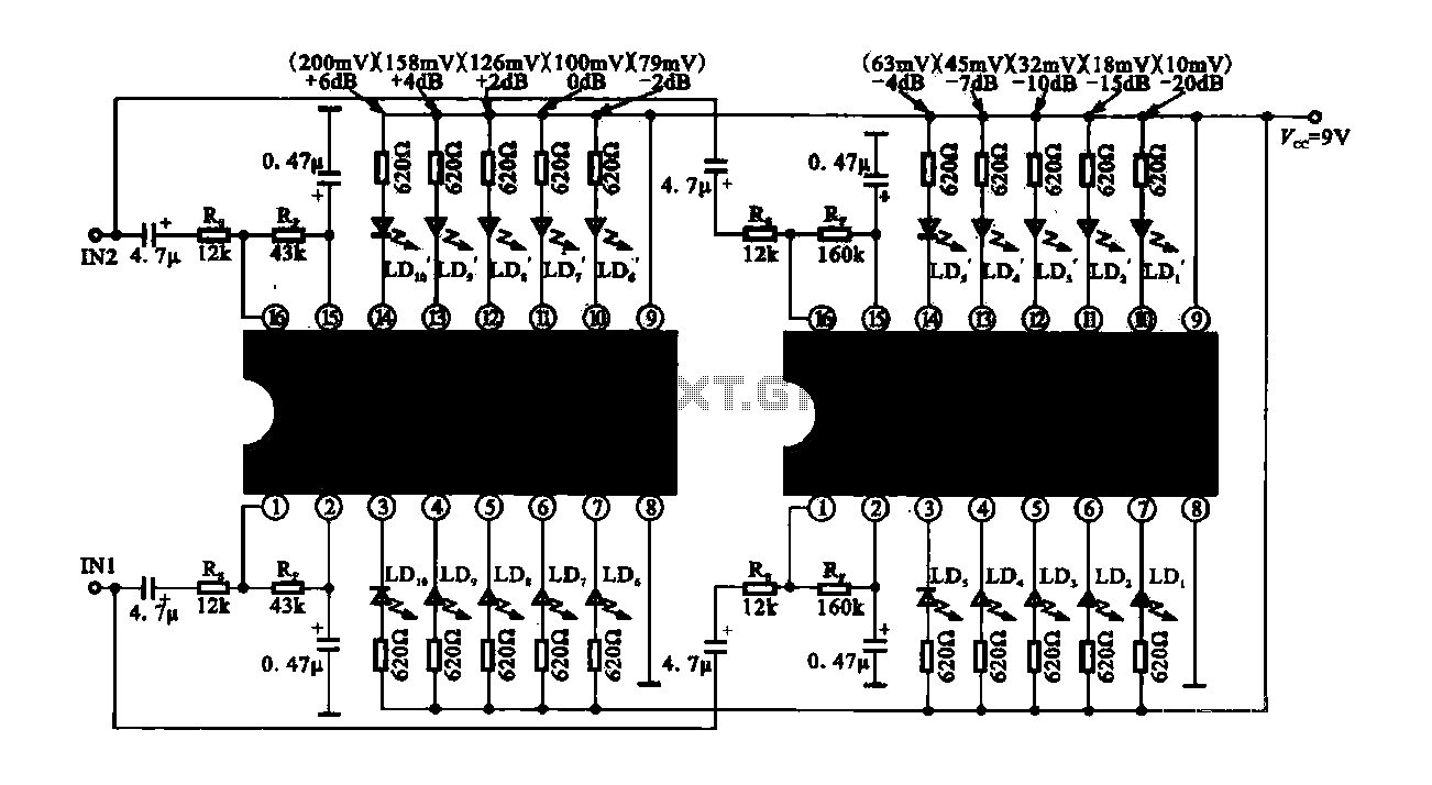
The circuit consists of dual drive integrated circuits (ICs) utilized in a 10 LED level meter configuration. The schematic features two TLM8101 driver ICs, which can be employed as alternatives. The 10 LED level meter circuit is designed to provide...
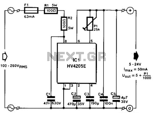
Direct derivation of 5 to 24 Vdc from AC mains without a transformer is possible with this circuit. Note that a direct mains connection to the DC output exists. Suitable safety precautions must be taken. This circuit design allows for...
The circuit consists of two main components: (1) a power supply circuit featuring a transformer (T) that steps down AC 220V to 33V, followed by a full-wave rectifier, a filter, and a three-terminal regulator that outputs +24V. This circuit...
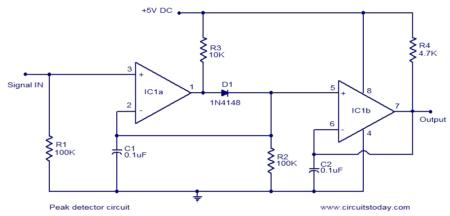
LM339-based peak detector circuit. Simple and easy to construct. Operates from a 5V DC single supply. LM339 is a dual comparator. The LM339-based peak detector circuit is designed to capture and hold the peak value of an input signal. This...