
H-bridge driver circuit composed by the Smart SIPMOS
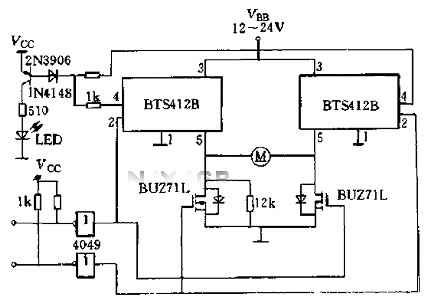
The circuit utilizes the BTS412B high-side power MOSFETs to efficiently manage the direction and power delivery to the DC motor. Each high-side switch is capable of handling significant currents, ensuring robust performance in demanding applications such as automatic doors. The BU271L low-side switches complement the high-side configuration, allowing for complete control over the motor's operation, including forward and reverse motion.
The integration of CMOS logic levels for controlling the H-bridge provides a reliable and efficient means of managing the switching states. This logic interface allows for seamless communication between the control system and the power stage, enabling precise control over the motor's operation. The use of an LED indicator for fault status enhances the system's reliability, providing visual feedback in the event of a malfunction.
The design includes a safety feature whereby the left leg midpoint resistance of 12kΩ acts as a safeguard against misinterpreting an open load condition. This is critical in ensuring that the system does not erroneously assume a fault when the motor is simply not engaged. The right BTS412B's ability to detect actual open load conditions and signal a fault helps maintain the integrity of the system, allowing for timely maintenance or intervention.
Overall, this H-bridge configuration is well-suited for applications requiring bidirectional motor control, with built-in fault detection and robust switching capabilities, making it an ideal choice for automatic door systems. BTS412B as two high-side power MOSFET switch and two BU271L (50v, Zhang 1n) for the low-side switch, can be composed of bi-directional H-bridge DC motor drive circuit shown in Figure 11-1l. The circuit is an electrical automatic doors design, continuous current up to 6A. Four-leg switches are directly controlled by CMOS logic levels. Two BTS412B state output of the logical drive or a transistor, the LED displays the fault status. Left leg midpoint -to-ground resistance when 12ktl four H-bridge switches are turned off, will not be BTS412B mistaken Open load. Once open load occurs, the right of BTS412B can detect it and issue a fault signal.
Related Circuits
A milliamp meter can function as a voltmeter by incorporating a series resistance. The required resistance is calculated by dividing the full-scale voltage reading by the full-scale current of the meter movement. For instance, using a 1 milliamp meter...

This circuit is based on the Sharp GP1U52X infrared module and the 1NS8048L microprocessor. The GP1U52X is a hybrid integrated circuit and infrared detector that provides a strong, clean signal for subsequent filtering and demodulation. The circuit utilizes the Sharp...
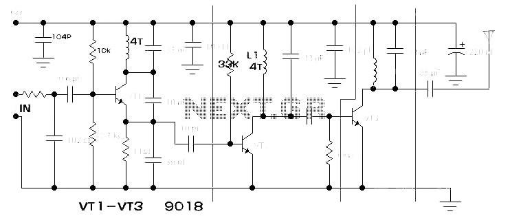
The components available were utilized to create a long-range FM radio transmitter operating within the 88-108 MHz band, designed for playing music. The circuit includes a power section that rectifies mains voltage to provide a stable 12V DC for...
The primary function of the optical receiver is to extract information encoded on a modulated light carrier from a distant transmitter and restore it to its original form. A typical through-the-air communications receiver can be divided into five distinct...
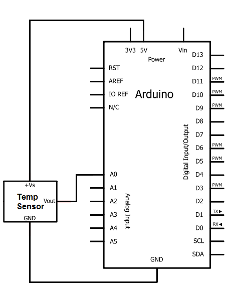
The integrated circuit (IC) used for temperature measurement is the TMP36. This IC will be integrated with an Arduino to obtain temperature readings. The Arduino will read the measured value from the TMP36 and convert it into degrees Fahrenheit,...
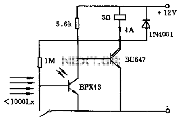
In the circuit's resting (dark) state, current flows through the electromagnet M. When light shines on the phototransistor, it turns on, causing the final stage transistor to enter the OFF state, which releases the solenoid. A 1M ohm feedback...
Warning: include(partials/cookie-banner.php): Failed to open stream: Permission denied in /var/www/html/nextgr/view-circuit.php on line 713
Warning: include(): Failed opening 'partials/cookie-banner.php' for inclusion (include_path='.:/usr/share/php') in /var/www/html/nextgr/view-circuit.php on line 713