
Photo interrupter circuit diagram
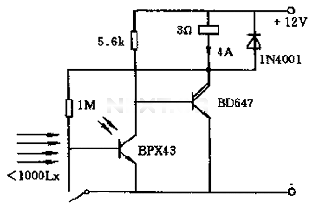
The described circuit operates on a principle of light sensitivity and feedback control. Initially, in the dark state, the electromagnet M is energized, allowing a current to flow that keeps the system in a ready state. The phototransistor acts as a light sensor; when illuminated, it activates, which subsequently deactivates the final stage transistor. This deactivation results in the solenoid being released, indicating a change in the circuit state from active to inactive.
The inclusion of a 1M ohm feedback resistor plays a crucial role in maintaining the transistor’s state. This feedback mechanism allows the circuit to retain its activated state even after the light source is removed. The time-sensitive nature of the transistor is critical for ensuring that the circuit remains responsive to transient changes in light conditions.
The reset mechanism is straightforward; pressing the reset button T reverts the circuit back to its original state, allowing for repeated operation. This functionality is essential for applications where the circuit needs to be reset frequently without manual intervention in the light detection process.
Furthermore, the option to use a Darlington transistor as an amplifier enhances the circuit's performance by providing a higher current gain. This characteristic is particularly beneficial in applications requiring substantial amplification of the input signal from the phototransistor, thereby improving overall sensitivity and responsiveness of the circuit.
Overall, this circuit design effectively integrates phototransistor operation, feedback mechanisms, and amplification to create a versatile system suitable for various electronic applications. Circuit at rest (dark) state operation the electromagnet M current flows, once there is sufficient strength so that light shines on the phototransistor is turned on, that is th e final stage transistor is in the OFF state, the solenoid release. Because by 1M ohm feedback to the photosensitive base of the transistor effect, so that even light cancel time-sensitive transistor is still turned on. Until press the reset button T, in order to return to the initial state. Darlington transistor which can be used in place of an amplifier greater magnification.
Related Circuits
This circuit functions to monitor the duration of occupancy in a toilet, activating an alert if the time spent exceeds a predefined limit. The components involved include a resistor, integrated circuit (IC), capacitor, and transistor. The occupancy monitoring circuit is...
Assistance is needed in analyzing a circuit, specifically regarding the frequency cut-off between the bass and treble channels. The potential cut-off frequencies under consideration are 500Hz, 1KHz, or 5KHz. In audio processing circuits, the frequency cut-off point between bass and...

The multi-purpose signal generator circuit consists of integrated circuit oscillators and frequency dividers. It generates square waves ranging from high frequencies to sub-audio frequencies and also produces a frequency standard in the VHF range. The alternative oscillator section feeds...
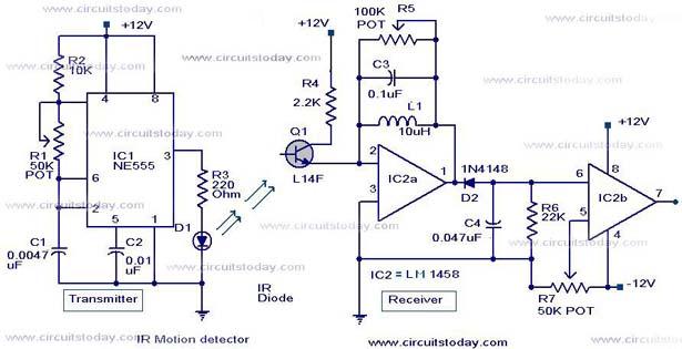
Infrared (IR) Motion Detector Circuit featuring a motion detector alarm and an infrared sensor. The circuit diagram and its operation are provided in detail. The infrared (IR) motion detector circuit is designed to detect motion within a specified range and...
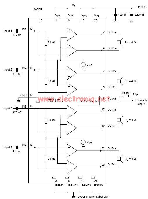
This electronic circuit diagram represents an audio power amplifier utilizing the TDA8571J integrated circuit. It is a class-B output amplifier configured in a BTL (Bridge-Tied Load) arrangement, featuring four amplifiers, each with a gain of 34 dB. The main...
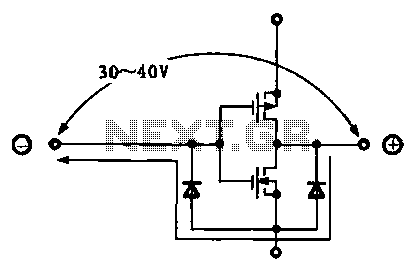
Due to the varying conditions of different input signals, when an abnormal voltage is applied to the pin, protection circuits are designed to create a circuit path that secures the internal protection of large-scale integration (LSI) circuits. The structure...