
Temperature Sensor Circuit
The TMP36 temperature sensor is a versatile and user-friendly device, ideal for integration with microcontrollers such as the Arduino. Its low operating voltage range allows for seamless compatibility with the Arduino's power supply, ensuring stable performance. The three-pin configuration simplifies connections, with one pin dedicated to the ground, another for the positive voltage supply, and the third for the analog output signal.
When the TMP36 is powered, it generates an output voltage that varies linearly with temperature. The output voltage can be calculated using the formula: V_out = (T in °C × 0.01V) + 0.5V, where T is the temperature in degrees Celsius. The Arduino's analog-to-digital converter (ADC) interprets this output voltage as a digital value between 0 and 1023, corresponding to the input voltage range of 0V to 5V.
To convert the Celsius temperature to Fahrenheit, the following formula is utilized: F = (C × 9/5) + 32. This conversion is implemented in the Arduino code, allowing users to read temperature in Fahrenheit directly from the computer interface.
The USB connection facilitates communication between the Arduino and the computer, enabling the upload of the program that processes the temperature data. The program typically includes initialization of the serial communication, reading the analog value from the TMP36, converting it to Celsius, then to Fahrenheit, and finally outputting the results to the serial monitor for easy viewing.
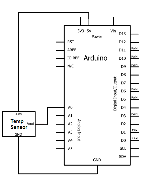
The inclusion of a delay function allows for periodic temperature readings, which can be modified according to user preferences or specific application requirements. This flexibility makes the TMP36 and Arduino combination suitable for various temperature monitoring projects, ranging from simple hobbyist applications to more complex environmental monitoring systems.The IC we will use to measure the temperature is the TMP36 IC. We will integrate this with the arduino to measure the temperature. The arduino will then read this measured value from the TMP36 and translate into degrees fahrenheit which we will be able to read from the computer. The TMP36 is a low voltage IC which uses between 2. 7V and 5. 5V of pow er. This is ideal because the arduino`s power pin gives out 5V of power. The IC has just 3 pins, 2 for the power supply and one for the analog output. The output pin provides a voltage output that is linearly proportional to the celsius (centigrade) temperature. In order to get the temperature in fahrenheit, we have to write code to the arduino to convert this celsius temperature into fahrenheit.
The code is shown below. Pin 1 receives positive DC voltage in order for the IC to work. This, again, is voltage between 2. 7-5. 5V. Pin 3 is the ground, so it receives the ground or negative terminal of the DC power supply. And Pin 2 is the output of the IC, outputting an analog voltage in porportion to the temperature it measures. Also to do this project we need a USB cable with a Type A connector on one end and a Type B connector on the other end.
This is so that we can hook our arduino to a computer and send it code that it can run to dispaly to us the temperature. Now that we have this circuit setup, we now connect the USB cable from the arduino to the computer. The type B side of the connector goes into the arduino and the type A side into the USB port of the computer.
Now the computer is connected to the arduino. We can now write code in the processing software to give instructions to the arduino. The code will now be explained. Before we can get a celsius or fahrenheit reading of the temperature, the analog output voltage must first be calculated. This will be the raw value (between 0 and 1023) divided by 205. It is divided by 205 because a span of 1024 values occupies 5V, or 1024/5= 205 per volt. At the end of this program, we put a delay of 5000ms to take the temperature reading every 5 seconds.
You can adjust this value to meet your personal preference or program needs. 🔗 External reference
Related Circuits
This hybrid circuit uses a mixture of transistors, an IC and a relay and is used to automatically open or close a pair of curtains. Using switch S3 also allows manual control, allowing for curtains to be left only...

The following instructions outline the process for constructing a practical test tool designed for troubleshooting and analyzing digital and microcontroller circuits. The complete assembly and instruction manual can be downloaded from the provided web link: Don's Projects. To begin,...

This article lists various types of audio amplifier circuits using MOSFETs. All circuits have been tested in a laboratory environment and have shown satisfactory performance. The amplifier utilizes one transistor, two MOSFETs, and a few resistors and capacitors in...

This 555 timer is designed uniquely to provide a positive output through control over its reset pin. Typically, the 555 timer IC is triggered by applying a negative voltage. The 555 timer is a versatile integrated circuit widely used in...

The digital time clock circuit is of great interest to electronic amateurs. The most popular clock ICs include the LM8361 and MM5387. Unfortunately, these ICs... The digital time clock circuit serves as an essential component for various electronic applications, providing...

The circuit for a SIM card reader is presented here. It utilizes a CMOS hex inverter along with other basic components. Not only does it function effectively, but it is also capable of communicating with a PC through a...