
H-Bridge Motor Driver using MOSFETs and Transistors
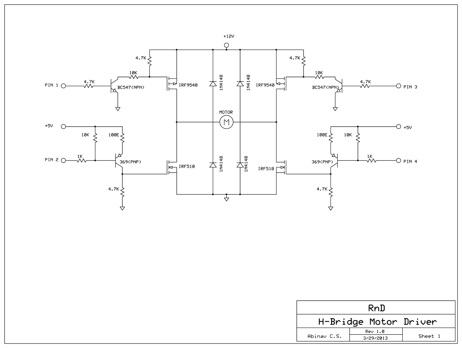
The H-Bridge Motor Driver circuit is an essential component in various applications, including robotics and automation, where bidirectional control of a motor is required. The circuit consists of four switching elements, typically MOSFETs or transistors, arranged in an 'H' formation. These switches control the flow of current through the motor, allowing it to rotate in either clockwise or counterclockwise directions.
In operation, the H-Bridge can be controlled by applying signals to the gates of the MOSFETs. For instance, turning on switches S1 and S4 allows current to flow through the motor in one direction, while activating switches S2 and S3 reverses the current flow, thus reversing the motor's direction. This capability is crucial for applications that require precise control over motor movement.
Additionally, when all switches are turned off, the motor is effectively disconnected from the power source, allowing it to coast to a stop. This feature is beneficial for energy efficiency and helps to prevent unnecessary power consumption when the motor is not in use.
In a typical implementation, the control signals for the MOSFETs can be provided by a microcontroller or a dedicated motor driver IC. The choice of MOSFETs should be based on the motor's voltage and current ratings to ensure reliable operation. Proper heat dissipation mechanisms, such as heat sinks, may also be necessary to manage thermal performance during operation.
The comprehensive understanding of the H-Bridge circuit's operation, along with its configuration and control mechanisms, is vital for engineers and designers working with motor control applications.In this post, we shall be covering on how to construct a H-Bridge Motor Driver circuit using simple MOSFET`s and Transistors. The main feature of this H-Bridge is that the motor can be driven in both directions. AnH-bridgeis a circuitthat allows a voltage to be applied across any load, like a motor in our experiment, in dual directions.
The `H` h ere just represents the formation of the circuit and has no reference to anyone. The H-bridge arrangement is generally used to reverse the polarity of the motor and to let the motor `free run` to a stop, as the motor is effectively disconnected from the circuit. The following table summarizes operation, with S1-S4 corresponding to the diagram above. 🔗 External reference
Related Circuits
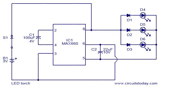
This is a simple LED torch circuit based on the MAX660 integrated circuit from MAXIM semiconductors. The MAX660 is a CMOS monolithic voltage converter IC capable of driving three bright white LEDs connected in parallel to output pin 8....
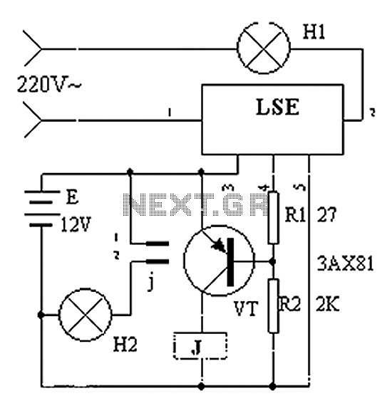
The circuit operation principle of the device illustrated in Figure 11 addresses the frequent occurrence of power outages, particularly in critical situations where continuous power supply is essential, such as during surgeries. The circuit employs a simple design that...

The design of a PAR 38 LED spotlight focuses on delivering practical LED lighting systems that meet performance expectations by reducing power consumption, extending lifespan, and enhancing overall efficiency. The PAR 38 LED spotlight is a widely used lighting solution...
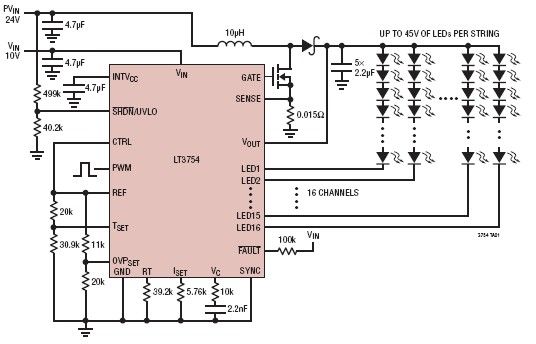
The LT3754 is a 16-channel LED driver featuring a step-up DC-DC controller developed by Linear Technology. It is designed to drive LEDs with a voltage of up to 45V. Each channel of the LT3754 LED driver is equipped with...
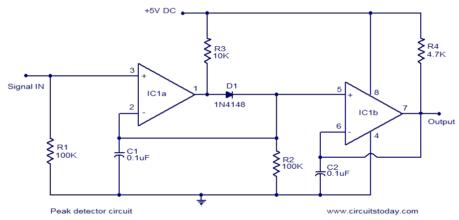
LM339-based peak detector circuit. Simple and easy to construct. Operates from a 5V DC single supply. LM339 is a dual comparator. The LM339-based peak detector circuit is designed to capture and hold the peak value of an input signal. This...
This circuit is a radio frequency (RF) oscillator that operates around 100 MHz. The audio is picked up and amplified by the electret. The RF oscillator circuit described operates at a frequency of approximately 100 MHz, making it suitable for...