
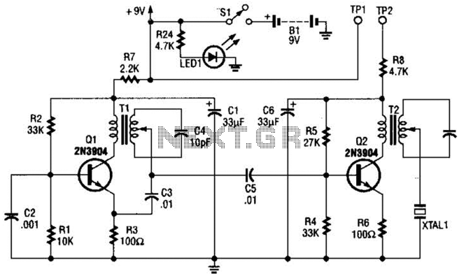
Two Transistors FM Transmitter
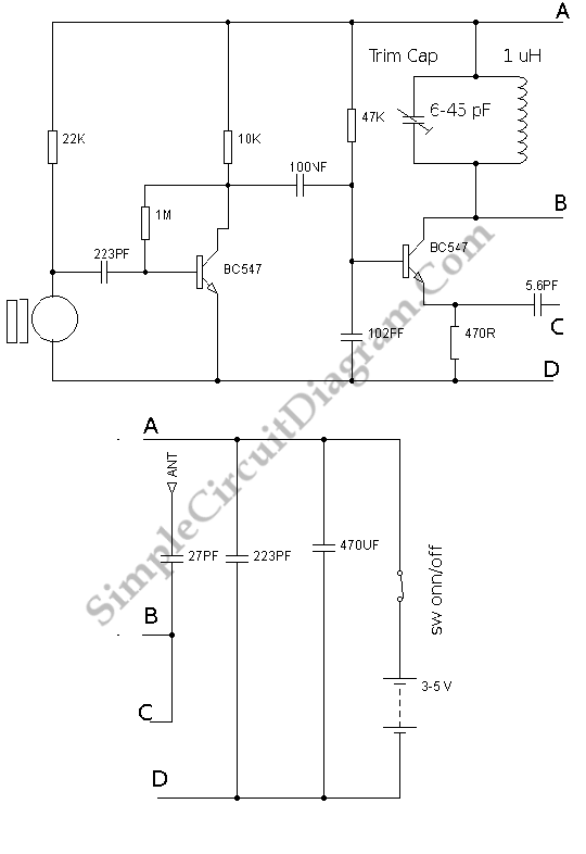
The RF oscillator circuit described operates at a frequency of approximately 100 MHz, making it suitable for various applications, including RF transmission and signal modulation. The core component of this circuit is the oscillator, which generates a continuous wave signal at the specified frequency.
To achieve the desired oscillation, the circuit typically employs a combination of inductors and capacitors to form a resonant LC circuit. This resonant circuit is crucial for determining the oscillation frequency, as it allows for selective frequency tuning. Additional components, such as transistors or operational amplifiers, may be used to amplify the signal and enhance the oscillator's stability.
The electret microphone serves as the input device for audio signals. It converts sound waves into electrical signals, which are then amplified to ensure sufficient strength for further processing. The amplified audio signal can be mixed with the RF signal generated by the oscillator, enabling the modulation of the RF carrier wave with the audio information. This modulation process is essential for transmitting audio signals over radio frequencies.
Overall, this RF oscillator circuit, combined with an electret microphone, forms a fundamental building block for audio transmission systems, allowing for wireless communication of sound signals. Proper design considerations, including component selection and circuit layout, are essential to optimize performance and minimize interference in practical applications.Basically, this circuit is a radio frequency (RF) oscillator that operates around 100 MHz. The audio which is picked up and amplified by the electret.. 🔗 External reference
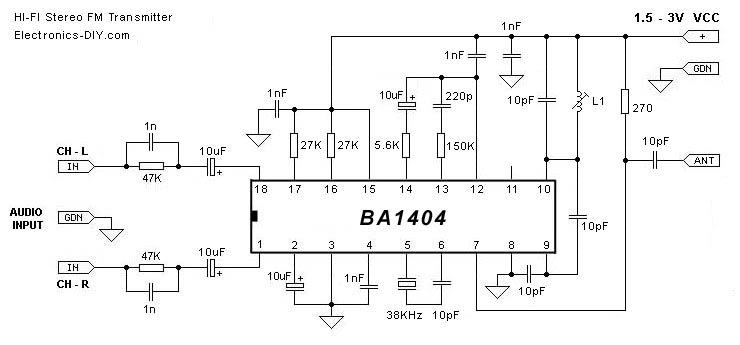
Related Circuits
Maxim has introduced a series of five integrated oscillator building blocks in the MAX260x series, covering a frequency range of 45 to 650 MHz. The MAX2606 is designed for the VHF band, allowing frequency variation of approximately ±3 MHz...
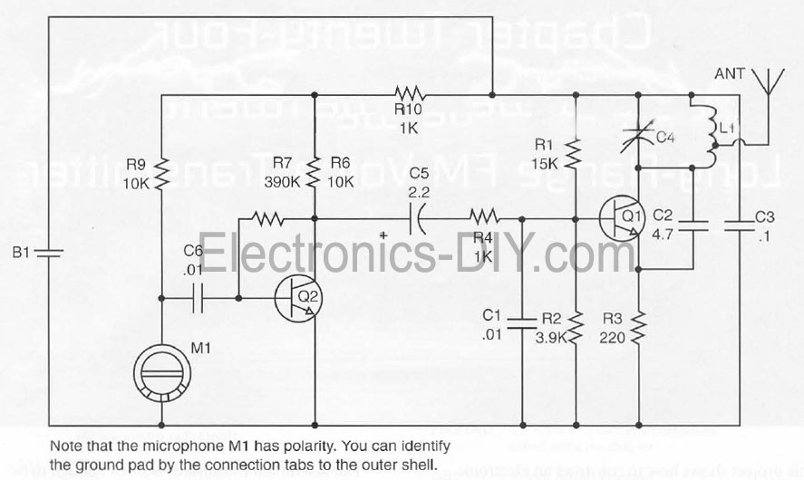
This document presents a Long Range FM Transmitter circuit, which is a highly sensitive, low-power FM transmitter. It includes a radio frequency (RF) oscillator section connected to a high-sensitivity, wide pass-band audio amplifier and a capacitance microphone equipped with...
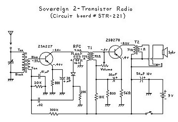
An analysis of certain radios reveals the impressive engineering by Japanese designers, particularly in creating a radio capable of driving a speaker with only two transistors. The first transistor (Q1) serves a dual function; it operates as an RF...
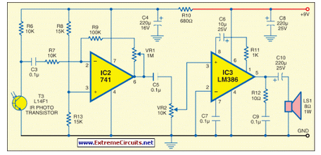
This circuit generates audio musical notes that can be heard from a distance of up to 10 meters. The circuit is divided into two parts: an infrared (IR) music transmitter and a receiver. The circuit operates on the principle of...
The transmitter features a VXO circuit that drives a keyed amplifier. This keyed amplifier powers an MRF 476 final amplifier, producing approximately 2 watts of output. Additionally, a solid-state T-R switch is incorporated for the receiver. The component values...
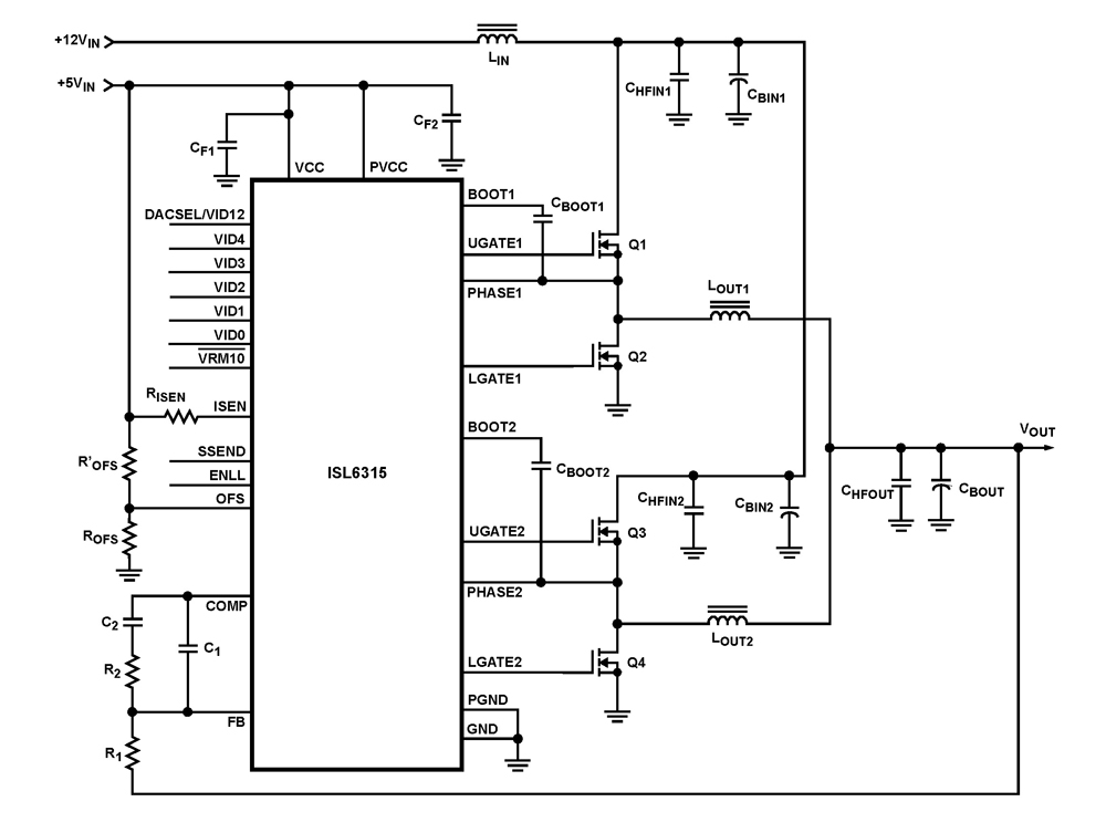
The ISL6315 two-phase PWM control integrated circuit (IC) offers a precise voltage regulation system capable of handling advanced loads ranging from 60A to 80A. Multiphase power conversion represents a significant shift from traditional single-phase converter configurations, which are increasingly...