
H bridge switch for small motors
The described circuit functions as a H-bridge motor driver, which allows for the control of a DC motor's direction and operation based on two input signals, A and B. The H-bridge configuration consists of four transistors (Tr1, Tr2, Tr3, Tr4) arranged in such a way that enables the motor to be powered in either direction or to be turned off entirely.
When both inputs A and B are in a high state (or open circuit), the transistors are configured to connect both terminals of the motor to ground (0V), effectively preventing any voltage from being applied across the motor. This state is often referred to as the "brake" state, where the motor is held stationary.
To drive the motor forward, input A is set to low (0V). This action turns on transistor Tr2, which allows current to flow from the power supply through the motor and back to ground via Tr2. The other transistors (Tr1, Tr3, Tr4) remain off, ensuring that the current flows in the correct direction to drive the motor forward.
Conversely, to reverse the motor's direction, input B is set to low. This activates transistor Tr6, which enables current to flow in the opposite direction through the motor. In this case, Tr2 remains off, and the current flows from the power supply through the motor and back to ground via Tr6, thus reversing the motor's rotation.
If both inputs A and B are set to low, both ends of the motor become connected to the high state (supply voltage), resulting in no potential difference across the motor terminals. Consequently, the motor is turned off, effectively stopping any motion.
This H-bridge design allows for precise control of the motor's operation, making it suitable for various applications, including robotics, automation, and motor control systems. Proper selection of transistors capable of handling the motor's current and voltage ratings is crucial for reliable operation, and additional components such as diodes may be included to protect against back EMF generated by the motor during operation.Two inputs, A and B, control the bridge. With both high (or open circuit) both ends of the motor are connected to 0v. Connect A low and Tr2 turns on causing the motor to go forward. Connect B low and Tr6 turns on, reversing the motor. If A and B are both low, both ends of the motor are high, so the motor is off. 🔗 External reference
Related Circuits
A one-inch reed switch with 40 turns effectively activates with the current flowing through a 150-watt lamp (approximately 625 mA), though larger reed switches may necessitate additional turns. If the master appliance draws less current, which is uncommon for...

A simple 16-volt switching power supply circuit can be constructed using the provided diagram, which is based on the MAX668 constant-frequency, pulse-width modulating (PWM), current-mode DC-DC controller. This integrated circuit is designed for a wide range of DC-DC conversion...
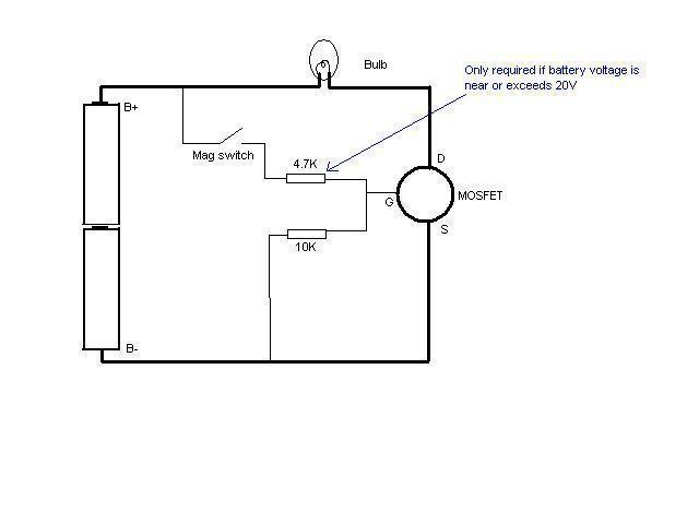
In this schematic provided by Jimmy M, will this circuit drain the batteries when the light is not in use? There is consideration for building a MOSFET circuit to be used in a compact application, where the original bulky...
A relay is controlled by a closed circuit in a digital logic setup, utilizing a touch input switching circuit. The described circuit involves a relay that operates based on a closed circuit condition within a digital logic framework. The relay...
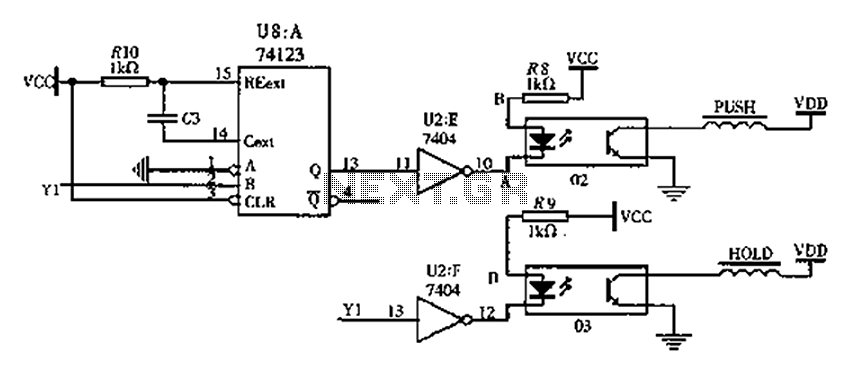
The FIG switching solenoid driver circuit utilizes the 74123 device chip (U8) and solid-state relays (02, 03). The switching electromagnet coil is referred to as the PUSH coil, while the HOL is maintained at a power supply voltage (VDD)...
The HandyBoard operates both pads using the positive supply from the battery. When one of the motors is intended to turn, the HandyBoard activates the corresponding pin to 0V. The voltage difference between the two pads causes the motor...