
Switching solenoid drive circuit diagram
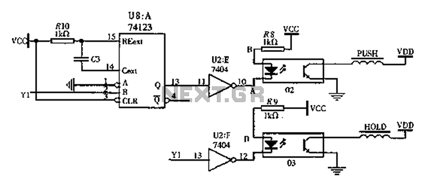
The circuit design involves several key components and their interactions. The 74123 monostable multivibrator (U8) serves as the primary control element, generating a pulse output when triggered by the input signal at pin Y1. The output pulse duration (T) is critical for ensuring that the switching solenoid operates effectively without overheating. The values of R10 (1000 ohms) and C3 (1000 microfarads) are chosen to achieve the necessary timing characteristics, allowing for a pulse width of 1 second.
The solid-state relays (SSR 02 and 03) act as electronic switches that control the high current flowing through the PUSH coil. When the output from the 74123 is activated, the SSRs conduct, allowing current to flow through the electromagnet coil, generating a magnetic field strong enough to actuate the solenoid. The use of solid-state relays enhances the reliability and efficiency of the circuit, as they provide faster switching times and longer lifespans compared to traditional mechanical relays.
The inverter (7404) inverts the output signal from the 74123, ensuring that the solid-state relay is activated correctly during the pulse duration. The design must consider the load characteristics of the solenoid, as the electromagnetic force generated must be sufficient to overcome any opposing forces, such as the return spring.
Overall, this circuit provides a robust solution for controlling solenoids in applications requiring precise timing and reliable operation, such as in dual-fuel systems or automated machinery. Proper selection of components and careful attention to timing parameters are essential for optimal performance and longevity of the circuit.FIG switching solenoid driver circuit, wherein the device chip U8 is 74123, the device is a solid state relays 02, 03, the switching electromagnet coil is sucked PUSH coil, HOL D is maintaining its coil power supply VDD to 24V. Of course, when the switching mechanism to switch to dual-fuel operation, from the B input pin Y1 74123 from the low to the high jump, fans variations make the output of 74123 Q output of a transient high current pulse, duration of T. After the inverter 7404, the potential of UA A low point will appear the same width, the solid state relay input terminal 02 also has a current time by T, then solid state relay output 02 appears conduction time T.
During this time, a strong suction current through the switching electromagnet coil inhalation, inhalation generate sufficient electromagnetic force of the electromagnet core. Pulse width T choice should refer solenoid switch setting performance parameters necessary to meet the core requirements of inhalation, can not be too long cause the coil to burn.
T is by selecting values of resistor R10 and capacitor C3 is determined. The Department T takes 1 second, R10 1000, C3 1000 F. Speaking from the mechanism, the switch and the solenoid to maintain the current high-voltage gas solenoid operating current is the same mechanism: when Y1 1, the existence of the holding current, the iron core is maintained at the suction state; when Y1 0 when no holding current exists, to restore the original core extended position under the action of the return spring.
Related Circuits
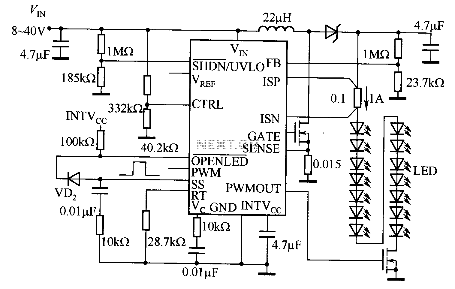
The LT3755 is utilized for high-side current sensing in LED strings, enabling flexible programming and control. It supports a PWM input that allows for a dimming ratio of up to 3000:1, while the CTRL input offers additional analog dimming...
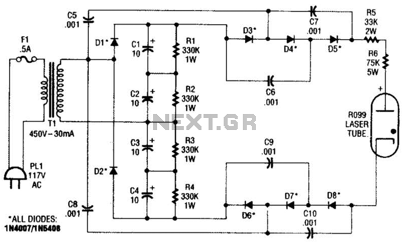
This supply generates an initial high voltage for ignition purposes. After ignition, the supply generates about 1300 to 1500 V. If a higher ignition voltage (than the 6000 V supplied) is necessary, more multiplier stages can be added to...
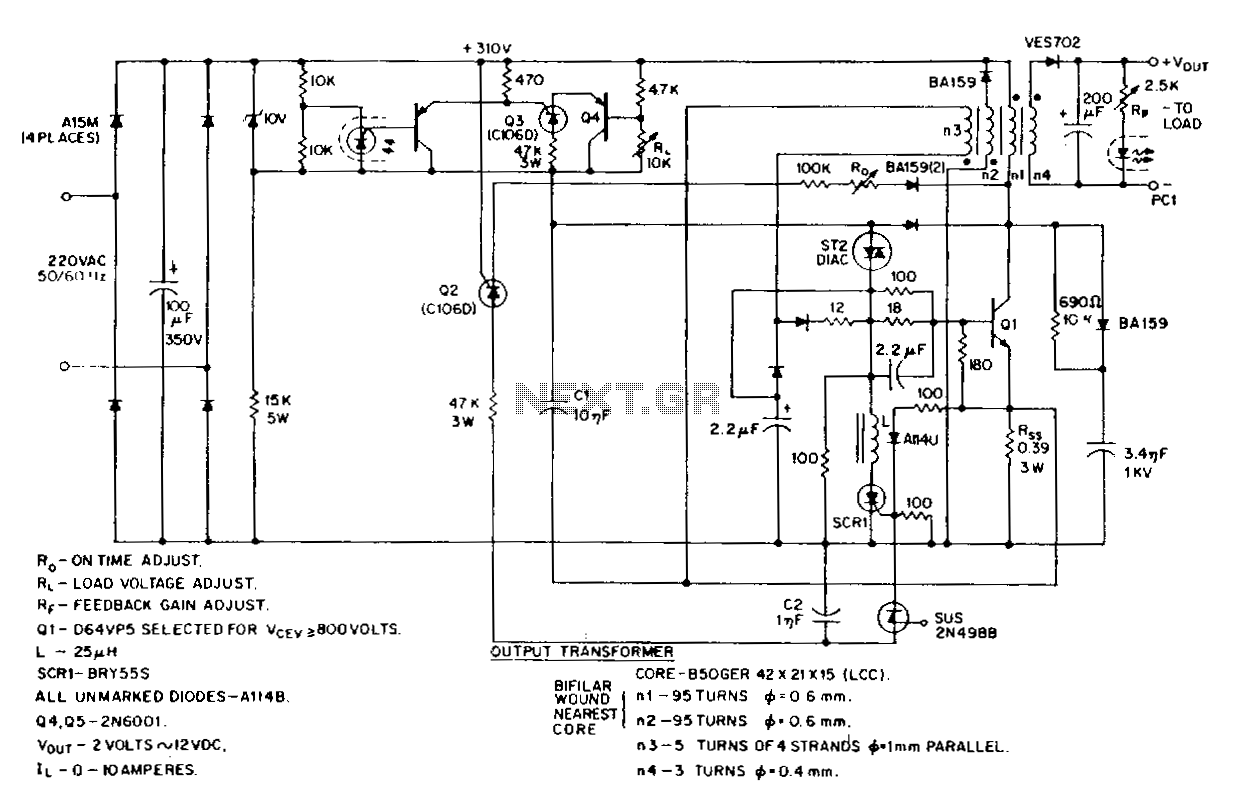
This low-voltage, high-current output switching power supply operates from a 220-V AC input. The circuit employs an ST2 diac relaxation oscillator, Q3, C1, and the diac to initiate conduction of the output switching transistor Q1. The on-time of Q1...
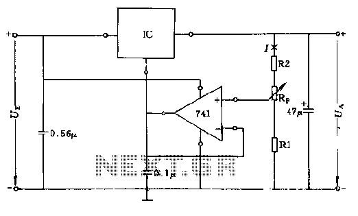
The circuit consists of resistors R1, R2, and RP, where the resistance values play a critical role in determining the magnitude of the current I. This current must exceed the input current of the operational amplifier, which is approximately...
VD represents the voltage drop across the diode, while VTrans indicates the voltage drop across the transistor. The boundary between continuous and discontinuous operation occurs when the output current (io) is zero. A primary consideration in converter design is...
The circuit depicted in Figure 3-131 utilizes a relay instead of a speed control relay. It is designed to operate effectively in dusty environments and other challenging conditions. The circuit operates by employing a relay as a primary switching mechanism,...